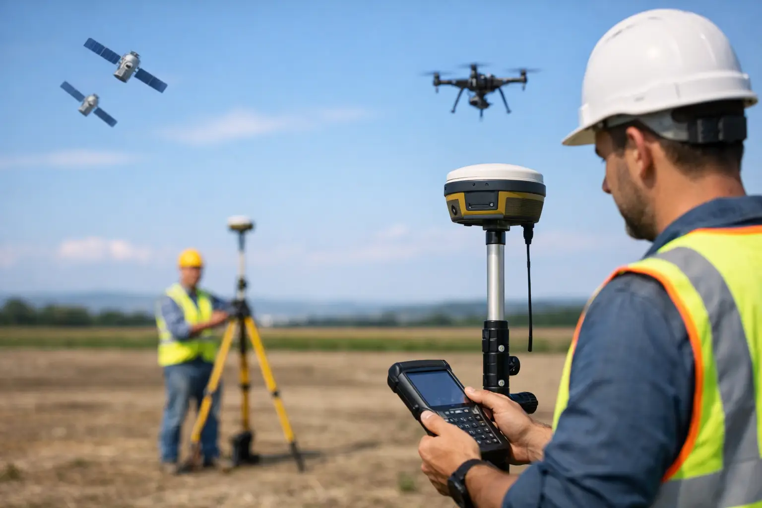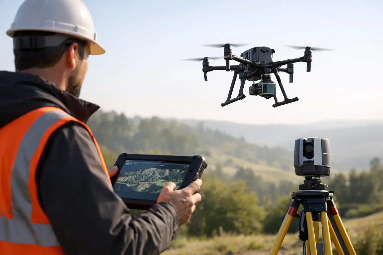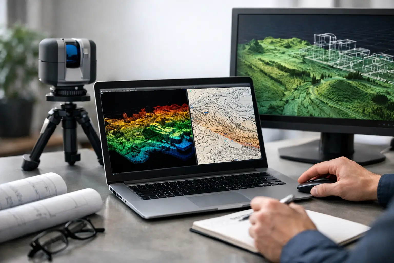
Author: GaryH

  • How to Process LiDAR Survey Data Accurately

    How to Process LiDAR Survey Data Accurately

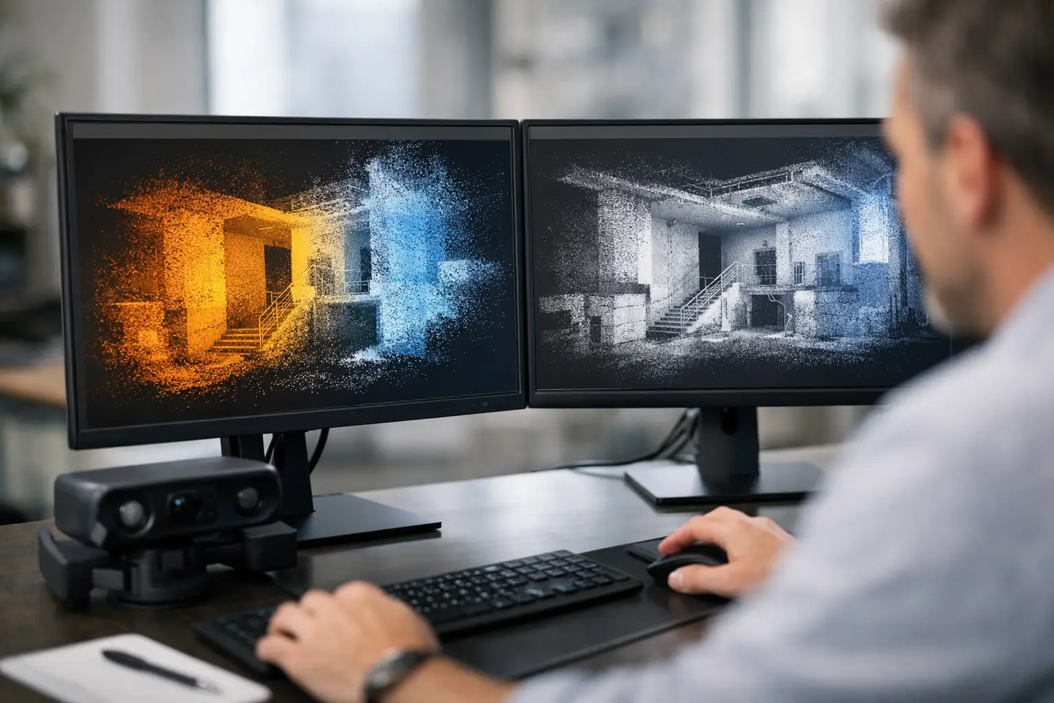
    A LiDAR survey is only as useful as the data delivered at the end of the workflow. A dense point cloud may look impressive, but it cannot support design, quantities, asset decisions or measured drawings until it has been correctly referenced, cleaned, classified and checked. Knowing how to process LiDAR survey data is therefore as important as selecting the scanner, drone or GNSS equipment used in the field.

    The right process depends on the capture method and required output. A mobile mapping scan of a road corridor, a terrestrial scan of an industrial structure and a drone LiDAR survey of a woodland site each create different processing challenges. The common objective is the same: produce an accurate, traceable dataset that is suitable for its intended use.

    Start with the required deliverable

    Processing should begin before files are imported. Define what the client, designer or asset team needs to receive. This might be a classified LAZ point cloud, a ground model, contours, a CAD drawing, a mesh model, stockpile volumes or a set of measured sections.

    This decision controls the processing tolerance. A planning-level terrain model does not need the same level of feature extraction as a detailed as-built survey. Likewise, a visually convincing mesh is not automatically appropriate for dimensional verification. Establish the required coordinate reference system, vertical datum, accuracy specification, survey boundary and exclusion areas at the outset.

    For UK projects, this commonly means confirming whether deliverables are required in OSGB36 / British National Grid and the relevant orthometric height datum. Confusion between ellipsoidal heights captured by GNSS and project levels can introduce significant vertical errors. Apply the correct geoid model and document the transformation used.

    Import and protect the source data

    Retain the original raw data in a controlled project folder before any processing begins. This includes LiDAR files, trajectory data, GNSS observations, IMU records, base-station files, photographs, control coordinates and field notes. Raw data is the audit trail if a question arises later about coverage, accuracy or a processing decision.

    Import the scan data into the chosen processing software in its native format where possible. LAS and LAZ are widely used for point-cloud exchange, while E57 is common for terrestrial laser scanning. Keep a clear naming convention for survey dates, scanner positions, flight lines and processing versions. On larger schemes, a small amount of file discipline prevents costly confusion when data is revisited months later.

    At this stage, inspect basic survey completeness. Check that all planned scan positions or flight lines are present, that no files are corrupt, and that the point density and coverage broadly match the site conditions. It is better to identify a missed area before processing time is spent on a model that will need to be remade.

    Georeference the survey correctly

    Georeferencing places the point cloud in the project coordinate system. The method depends on the equipment and survey approach. Terrestrial scanners may use surveyed targets, cloud-to-cloud registration, or a combination of both. Mobile and UAV LiDAR systems usually rely on GNSS and IMU data, supported by RTK, PPK processing or ground control.

    For GNSS-enabled workflows, review the correction source, base-station coordinates, observation quality and any reported fixed or float solutions. A fixed RTK status alone is not proof that the final point cloud meets specification. Obstructions, multipath, poor satellite geometry and an unsuitable control setup can still affect results.

    Where targets or control points are used, compare the measured point-cloud coordinates against independently surveyed coordinates. Distribute control across the site rather than concentrating it in one convenient location. Control should represent the full working area, including changes in elevation where relevant.

    Registration and strip alignment

    Registration aligns individual scans or LiDAR strips into one coherent cloud. Software can achieve close-looking overlaps while still leaving local error that matters for survey work. Inspect hard edges, building corners, kerbs, rails and other defined features in overlap zones. These reveal misalignment more clearly than vegetation or uneven ground.

    For UAV and mobile LiDAR, review strip alignment across parallel runs and at cross-lines where available. Systematic offsets may indicate trajectory issues, timing errors, IMU calibration problems or weak GNSS performance. Do not conceal these problems by applying broad adjustments without understanding their source.

    Clean the point cloud without removing evidence

    Raw LiDAR data contains more than the site. It can include passing vehicles, people, birds, rain artefacts, reflective surfaces, scanner noise and points beyond the useful survey area. Cleaning removes points that compromise the output while preserving data that may be needed for validation.

    Use a combination of automated filters and manual review. Automated noise filters are efficient, but aggressive settings can remove legitimate narrow features such as overhead wires, fence posts, sign supports and kerb edges. This is particularly relevant for utilities, rail, highway and asset-inspection surveys, where small objects may be the reason for commissioning LiDAR in the first place.

    Clip the cloud to the agreed site boundary only after confirming that no contextual data is needed outside it. A modest buffer can be useful for drainage assessment, earthworks design and modelling of site access routes.

    Classify points for the intended analysis

    Classification separates points into meaningful groups, such as ground, vegetation, buildings, roads, water, vehicles and infrastructure. It turns a large collection of measurements into a dataset that can be analysed and modelled efficiently.

    Ground classification is often the critical stage. The algorithm identifies the likely terrain surface by assessing local elevation changes, slopes and point relationships. It performs well on open ground, but can struggle around retaining walls, steep banks, dense undergrowth, spoil heaps and built-up areas. Parameters should be suited to the terrain rather than applied as a default across every project.

    Review the ground class closely at breaklines and abrupt level changes. If building points are incorrectly retained as ground, the resulting digital terrain model can create false high areas. If genuine ground is removed beneath low vegetation, the terrain model may be incomplete. In forestry, LiDAR penetration can provide valuable terrain coverage under canopy, but results depend on sensor specification, flying height, pulse density and the density of the vegetation itself.

    Build the right surface model

    A digital terrain model represents bare earth using ground-classified points. A digital surface model includes the visible upper surface, such as buildings, trees and vehicles. Neither is universally better; the appropriate model depends on the task.

    Use a terrain model for cut and fill calculations, drainage studies, route design and contours. Use a surface model for canopy height, visibility work, roof analysis and broad site context. Grid resolution should reflect point spacing and required accuracy. An overly fine grid can imply detail that the source survey does not support, while an overly coarse grid can smooth out operationally significant features.

    Check accuracy before creating final outputs

    Quality assurance should be a formal stage, not a quick visual check at the end. Compare independent check points to the final cloud or derived surface, rather than only assessing the control that was used to constrain the survey. Record horizontal and vertical residuals, along with the method used to obtain them.

    A practical QA review should confirm four areas:

    • coordinate system, datum and units are correct;
    • coverage meets the agreed survey extent;
    • point-cloud registration and strip alignment are within tolerance; and
    • independent check points support the stated accuracy.

    Also examine the dataset at the scale at which it will be used. A cloud that appears clean when viewed across an entire site may show duplicated façades, noisy edges or gaps when a designer zooms into a kerb line or steel connection. Accuracy, precision and point density are related but different measures. High point density does not correct poor georeferencing.

    Produce CAD-ready and analysis-ready deliverables

    Once the cloud has passed QA, export only the formats and layers required for downstream use. A classified LAZ file is efficient for archiving and specialist analysis. CAD users may need extracted linework, breaklines, contours, sections or an agreed surface format. Asset teams may require a registered point cloud, panoramic imagery and clearly identified features for inspection planning.

    Avoid supplying an unstructured, multi-gigabyte point cloud as the only deliverable unless that has been specifically requested. It transfers the processing burden to the client and may be impractical for their software or hardware. Clear layer naming, sensible clipping, a coordinate statement and a concise survey report make data easier to use and defend.

    For repeat surveys, use the same control strategy, coordinate system, classification rules and reporting method where possible. Consistency makes change detection, stock monitoring and asset comparison far more reliable.

    LiDAR Tech UK can support the full workflow, from selecting capture equipment and GNSS corrections through to processing and survey deliverables. The best result is not simply a detailed point cloud; it is dependable spatial information that your project team can use with confidence.


  • Inspection Drones for Infrastructure Projects

    Inspection Drones for Infrastructure Projects

    A bridge inspection delayed by lane closures, a wind turbine accessible only by rope team, or a transmission tower standing within a live network all present the same operational problem: the asset needs close, defensible inspection data without putting people in unnecessary danger. Inspection drones for infrastructure give asset owners a practical way to capture that evidence faster, more frequently and with far less disruption than many conventional access methods.

    For UK infrastructure teams, the benefit is not simply aerial imagery. A properly specified enterprise drone workflow can produce repeatable, geo-referenced records for condition assessment, maintenance planning, engineering review and audit trails. The value comes from matching the aircraft, sensor, positioning method and data output to the inspection decision that follows.

    Where infrastructure drone inspections add value

    Drone inspection is especially effective where access is difficult, risk is high or the cost of downtime is significant. Utilities, highways, rail-adjacent assets, industrial estates, ports, quarries and renewable energy sites all contain structures that are expensive to reach by scaffold, cherry picker, rope access or manned aircraft.

    A drone can document façades, roofs, stacks, bridges, retaining walls, pylons, cooling towers and drainage assets from safe stand-off distances. It can also survey broad corridors and sites between detailed inspections, helping teams identify change, vegetation encroachment, drainage issues or surface deterioration before sending people to investigate further.

    This does not mean drones replace every close-up inspection. Where an engineer needs to touch a component, take a material sample, test a connection or assess an area hidden behind a cover, physical access remains necessary. The strongest operational model is often drone-first: use aerial data to prioritise access work, define the scope precisely and avoid sending specialists to defects that do not require intervention.

    Choose the sensor around the defect, not the aircraft

    The most common procurement mistake is choosing a drone by headline flight time or camera resolution alone. For infrastructure work, the correct starting point is the defect or measurement requirement. A high-resolution visual camera is excellent for general condition records, concrete spalling, corrosion, loose fittings and visible cracking where the aircraft can safely get close enough. Optical zoom adds value on tall structures or in exclusion zones, allowing detail to be captured without compromising stand-off distance.

    Thermal imaging serves a different purpose. It can highlight temperature variation associated with electrical faults, insulation failures, solar-panel anomalies, heat loss or moisture-related issues. Thermal findings need experienced interpretation and appropriate environmental conditions. Reflections, solar loading, wind and changing surface temperatures can all affect the result, so a thermal image should be treated as inspection evidence rather than an automatic diagnosis.

    LiDAR is particularly useful when the required output is accurate 3D geometry. It can capture complex structures, corridors and vegetation-affected environments, producing point clouds that support clearance assessment, volumetric analysis, digital twins and change detection. Unlike photogrammetry, LiDAR does not rely on visible texture in the same way, although its accuracy still depends on sensor calibration, flight planning, GNSS conditions and control.

    Photogrammetry remains a highly capable option for detailed orthomosaics and textured 3D models. With sufficient image overlap, stable lighting and sound ground control, it can create useful survey-grade deliverables. It is often more economical than airborne LiDAR for large, open and visually detailed surfaces. The choice depends on the required tolerance, surface type, vegetation cover and the software workflow used by the engineering team.

    Positioning and repeatability determine whether data can be compared

    A single inspection can identify an obvious fault. The longer-term advantage comes from comparing inspection datasets over time. To do this reliably, image positions and 3D datasets need consistent spatial reference.

    RTK-enabled enterprise drones can improve positional accuracy by applying real-time corrections from a base station or network correction service. For many projects, this reduces the time required to establish conventional ground control and strengthens the location confidence of collected imagery. It does not eliminate the need for verification. On high-accuracy work, independent check points, a documented coordinate system and clear processing controls remain essential.

    Repeatability also depends on flight design. Teams should record stand-off distance, camera angle, focal length, altitude, overlap and inspection route, rather than relying on a pilot to recreate a previous flight from memory. Repeat missions around a bridge bearing, tower face or rooftop plant area should use the same inspection geometry wherever practical. Consistent capture makes change easier to detect and reduces ambiguity in engineering review.

    Accuracy should be specified in the final deliverable

    It is useful to separate aircraft positioning accuracy from the accuracy of the final model, measurement or defect location. GNSS performance, image quality, surface geometry, control points and processing settings all contribute. A project brief should state what is required: for example, a visual report with defect locations, a scaled orthomosaic, a classified point cloud, a CAD-ready model or a measured clearance survey.

    Without that definition, teams can collect impressive-looking data that does not answer the maintenance question. A professional workflow begins with the output, then specifies capture and processing to achieve it.

    Plan the operation as carefully as the flight

    Infrastructure environments create constraints that consumer-drone workflows are not designed to manage. Live substations, operational railways, public highways, industrial traffic, confined spaces, cranes, turbines and high winds require structured planning. The pilot must understand airspace, site hazards, electromagnetic interference, take-off and landing options, lost-link procedures and safe separation from people and assets.

    UK operators must also meet Civil Aviation Authority requirements applicable to the aircraft, operation and location. Depending on the proposed flight, this may involve defined competency, operational procedures, permissions or an Operational Authorisation. Clients should expect suitable risk assessments, method statements, insurance and records of pilot competence as part of a professional inspection mobilisation.

    Weather deserves more than a basic wind-speed check. Gusts around structures, rotor wash near walls, rain, low light, thermal contrast, cloud cover and sun angle can all determine whether a capture is safe and technically useful. A thermal survey planned for the wrong time of day can be less valuable than no survey at all. A visual inspection of a west-facing façade may need to avoid glare, while a LiDAR mission may require a different approach to manage occlusion.

    Turn drone capture into an asset management record

    Infrastructure managers do not need thousands of unstructured images handed over at the end of a flight. They need information that can be reviewed, assigned and compared. That may be a defect register with annotated photographs, a georeferenced map, a 3D point cloud, a mesh model, a thermal report or a set of CAD-compatible measurements.

    The right deliverable depends on the organisation’s existing systems. A highways contractor may need chainage-referenced imagery and dimensions. A utility provider may require asset IDs, coordinates and thermal anomalies in a standard inspection template. A civil engineering consultant may need point clouds and mesh data for design coordination. Establishing naming conventions, coordinate reference systems, file formats and acceptance criteria before fieldwork prevents expensive reprocessing later.

    Data governance also matters. Critical infrastructure imagery may be commercially sensitive or subject to site-specific security controls. Confirm where data will be stored, who can access it, how long raw files are retained and whether processing will take place within an approved environment. These considerations should sit alongside resolution and accuracy in the procurement discussion.

    Build the right capability model

    Some organisations benefit from owning an enterprise drone system and training their own team. This approach suits frequent, repeatable inspections where local staff can mobilise quickly and where a clear internal operating procedure can be maintained. Ownership should include more than the aircraft: batteries, charging and transport arrangements, RTK corrections, software licences, maintenance, pilot training, operational documentation and data-processing capacity all need to be budgeted.

    For periodic, technically complex or higher-risk work, an outsourced service can be more efficient. It provides access to experienced pilots, survey control, specialist sensors and established processing workflows without creating an internal compliance burden. A hybrid approach is also common: an in-house team captures routine visual checks, while specialist providers support LiDAR surveys, thermal programmes, complex airspace or engineering-grade deliverables.

    LiDAR Tech UK supports both routes, supplying enterprise drone and positioning systems alongside training, technical support, data processing and field services. The key is to choose a capability model that supports the inspection frequency, accuracy requirement and internal resource available – not simply the lowest initial equipment cost.

    A better question for procurement teams

    Rather than asking which drone is best, ask which inspection decision needs to be made faster and with greater confidence. That question clarifies the sensor, the accuracy, the operating model and the deliverable. When the workflow is designed around a real asset-management decision, drone data becomes a reliable maintenance tool rather than a collection of aerial photographs.

  • Best Software for Point Cloud Processing

    Best Software for Point Cloud Processing

    A point cloud can be captured in hours yet lose value quickly if registration is unstable, noise is left unresolved or the final model cannot move into the client’s CAD, BIM or asset-management workflow. The best software for point cloud processing is therefore not simply the package with the longest feature list. It is the one that produces dependable, usable deliverables at the required accuracy and within the time available.

    For UK survey, construction, infrastructure and inspection teams, software selection should begin with the outcome: a registered scan set, a classified terrain model, measured as-built information, a mesh for visualisation, or drawing-ready geometry. The right answer varies according to capture method, point-cloud size, required tolerances and the experience of the people processing the data.

    What point cloud processing software must do

    A professional workflow normally starts by importing LiDAR, terrestrial laser scan, mobile mapping or photogrammetry data. The software then aligns individual scans or trajectories, applies control where required, removes unwanted data, checks quality and exports a format suitable for downstream design or analysis.

    Registration is usually the critical stage. Target-based registration can provide clear auditability on controlled survey work, while cloud-to-cloud registration can reduce field setup time on complex interiors or large sites. Neither removes the need for sound survey control, sensible overlap and a documented accuracy check. Software can refine good data; it cannot reliably recover information that was never captured.

    Processing requirements then diverge. A highways survey may need ground classification and a clean digital terrain model. A building retrofit project may require a coordinated point cloud for Revit or AutoCAD workflows. An industrial inspection may demand high-detail meshing, measurement and colour imagery. Teams should avoid buying a platform designed around one task and expecting it to perform every specialist function equally well.

    Best software for point cloud processing by workflow

    Leica Cyclone REGISTER 360 PLUS

    Leica Cyclone REGISTER 360 PLUS is a strong choice for teams processing terrestrial laser-scanner data where efficient registration, visual quality checking and a clear project record matter. Its guided workflow is particularly useful when multiple operators need consistent results across building, plant and infrastructure surveys.

    The principal benefit is speed from field capture to a registered deliverable. Visual alignment tools and automated registration can reduce manual effort, but surveyors should still review constraints, residuals and control results before issue. It is best suited to organisations already operating within a Leica scanning ecosystem or regularly handling scan-intensive reality-capture projects.

    Its trade-off is commercial and operational: it is a specialist professional platform, so it makes most sense where scan registration is a regular, billable activity rather than an occasional requirement.

    Trimble RealWorks

    Trimble RealWorks is designed for survey and engineering workflows that require more than basic registration. It supports point-cloud processing, inspection, modelling and deliverables for construction, industrial and infrastructure applications. It is particularly relevant where data must be connected to established Trimble field and office processes.

    For teams creating as-built documentation, extracting geometry or checking construction against design, RealWorks offers capable tools without forcing every project into a general-purpose CAD workflow first. The practical consideration is training. Its capability is substantial, but users obtain better results when templates, export standards and quality-control procedures are agreed before projects begin.

    FARO SCENE

    FARO SCENE remains a practical registration and processing environment for FARO laser scanner users. It is well suited to organisations capturing building interiors, heritage sites, industrial facilities and construction progress data, particularly where automated registration can accelerate routine processing.

    The software performs best when field crews follow a repeatable capture plan with adequate overlap and appropriate targets or reference objects. It is not a replacement for survey control on work with defined coordinate and accuracy requirements. Where deliverables extend to modelling, CAD extraction or advanced analysis, SCENE is often part of a wider software chain rather than the only platform required.

    Autodesk ReCap Pro

    Autodesk ReCap Pro is often the sensible choice for project teams that need to bring registered point clouds into Autodesk design workflows. Its value lies in making reality-capture data accessible for AutoCAD, Revit and Civil 3D users who need context for design, coordination and measured verification.

    It is less suited to being the primary processing environment for complex, raw multi-scan datasets. A survey team may register and validate data in scanner-specific software, then use ReCap Pro to distribute, crop and prepare files for design colleagues. This division of labour can be efficient, provided file naming, coordinates and revision control are managed carefully.

    CloudCompare

    CloudCompare is a capable open-source option for visualisation, segmentation, comparison, distance analysis and point-cloud cleaning. It can be valuable for technical users who need to inspect data, compare epochs or carry out specific analytical tasks without adding another high-cost licence.

    Its limitation is not capability but workflow support. CloudCompare is less structured than commercial enterprise platforms and relies more heavily on user knowledge. It may be an excellent secondary tool for experienced geospatial professionals, but it is rarely the best sole platform for a business that needs repeatable reporting, vendor support and straightforward handover between staff.

    TerraScan and TerraModeler

    For airborne and mobile LiDAR projects, TerraScan and TerraModeler remain respected specialist tools for classification and terrain extraction. They are highly relevant to corridor mapping, forestry, utilities, flood-risk modelling and large-area topographic work where ground filtering and class accuracy determine the value of the final dataset.

    These tools reward experienced operators. Automated classification routines can be configured effectively, but vegetation, overhead lines, complex structures and variable terrain still require inspection and manual refinement. They are not aimed at a simple indoor scan-registration workflow; their strength is detailed geospatial processing at scale.

    Select software around the deliverable, not the scanner

    A scanner purchase should not dictate every office decision. Whether data comes from a terrestrial system, a wearable mobile mapper, an RTK-controlled drone or a vehicle-mounted platform, the required deliverable should determine the processing path.

    For survey-grade topographic output, prioritise coordinate-system handling, control adjustment, classification tools and exports that work cleanly in CAD and GIS. For building surveys, prioritise registration confidence, clipping, measurement, panoramic imagery and compatibility with BIM tools. For asset inspections, look for annotation, repeatable measurement, mesh generation and comparison tools that make change visible to engineering teams.

    Also consider point-cloud volume. A small internal survey can be managed on a standard workstation, while multi-day mobile mapping or high-density terrestrial scanning projects may require substantial RAM, fast storage and a dedicated graphics card. The cost of inadequate hardware is often measured in lost processing time and failed exports, not just slower rendering.

    Questions to ask before committing

    Before selecting a package, establish whether it can import your native scan or trajectory files without a slow conversion step. Confirm how it handles UK National Grid, local site grids and survey control. Ask what quality report can be produced, how licences are structured, whether processing can be repeated by another operator and which export formats your clients actually accept.

    It is also worth testing a real project rather than a clean demonstration dataset. Include reflective surfaces, vegetation, tight interiors, low-overlap areas or long corridors if those conditions are typical of your work. A trial should prove registration quality, processing time and the final handover format, not just confirm that the software opens a file.

    Build a dependable processing workflow

    The most effective software environment is usually a controlled combination: capture software for import and registration, a specialist tool for classification or analysis where needed, and design software for final coordination. Attempting to force every job through one package can create bottlenecks and reduce traceability.

    LiDAR Tech UK can help organisations match LiDAR capture hardware, processing software and practical training to the required survey or inspection output. The aim is a workflow that field teams can operate confidently and office teams can verify, repeat and deliver.

    Choose software that makes accuracy visible rather than assumed. When registration checks, coordinate control and export requirements are agreed before the first scan is taken, point-cloud data becomes a dependable project asset rather than another large file waiting to be processed.

  • A Point Cloud Registration Workflow That Works

    A Point Cloud Registration Workflow That Works

    A point cloud registration workflow is where a fast LiDAR capture either becomes dependable survey information or remains a collection of impressive-looking scans. The scanner may collect millions of points in minutes, but every scan position, trajectory segment and reference target must resolve into one coherent coordinate system before the data can support design, measurement or asset decisions.

    For UK survey, construction and infrastructure teams, registration is not simply a software task completed at the end of the day. It begins with planning the survey control, choosing sensible scan positions and ensuring enough overlap exists to constrain the final model. A well-planned workflow reduces office processing time, limits revisits and gives clients confidence that the deliverable can be used in CAD, BIM, GIS or inspection reporting.

    What registration must achieve

    Registration transforms separate point clouds into a single spatial dataset. Depending on the method, scans are aligned using common geometry, artificial targets, GNSS positions, SLAM trajectory data, surveyed control or a combination of these methods. The objective is not merely to make the dataset look aligned. It is to quantify, manage and document the accuracy of that alignment.

    The required result depends on the application. A rapid internal stockpile model may tolerate lower relative accuracy than a measured building survey or clash-sensitive retrofit scheme. A mobile mapping survey of a long highway corridor introduces different challenges again, including GNSS availability, trajectory drift and repeated visual features. The registration method should therefore follow the required deliverable accuracy, site conditions and available control, rather than the scanner specification alone.

    Relative accuracy and absolute accuracy should be considered separately. Relative accuracy describes how well scans fit one another within the point cloud. Absolute accuracy describes how well the completed cloud relates to the project grid, national grid or site control. A dataset can have excellent internal alignment while still being incorrectly positioned if the control has been entered, observed or transformed incorrectly.

    Plan control before the first scan

    Control is the foundation of a defensible registration. Before mobilisation, establish the coordinate reference system, vertical datum, project origin and required output format with the client or design team. On construction projects, confirm whether the contractor’s local grid is to be used and verify how it relates to OS National Grid and Ordnance Datum Newlyn where relevant.

    Control points should be stable, accessible and distributed across the survey area. Concentrating all control at one end of a site can produce a good local fit while allowing error to grow across the rest of the dataset. For a building, control around the perimeter and across different levels provides a stronger solution. For a linear asset, use suitable spacing along the route and allow for independent check points.

    GNSS/RTK can establish efficient control in open environments, provided correction availability, satellite visibility and multipath risk are assessed. In urban streets, beneath structures or within dense woodland, a total station traverse or closed control network may be more appropriate. The practical choice depends on the environment. The key requirement is traceable, verified coordinates rather than assuming an RTK fix alone is sufficient.

    Artificial targets remain valuable where high confidence is required. Spheres, chequerboard targets and surveyed marks give the registration software clear common features, particularly in areas with limited geometry such as long corridors, plain walls or repetitive industrial interiors. Targets must be visible from multiple scan positions and set where they cannot be disturbed by site activity.

    Capture for overlap, not just coverage

    A scan plan should create overlap deliberately. Coverage answers whether every required surface has been observed. Overlap answers whether the software has enough shared geometry to align adjoining scans reliably. These are related, but they are not the same.

    For static terrestrial scanning, each new scan should see a meaningful portion of the preceding scan and, where possible, connect to more than one neighbouring position. This creates loops in the network. Loops are useful because they expose cumulative error rather than allowing a chain of scans to drift unnoticed from one end of a structure to the other.

    Feature-rich areas generally register well using cloud-to-cloud alignment. Corners, structural steel, plant, façade detail and varied ground surfaces provide useful geometry. Large open floors, uniform tunnels, glazed elevations and repetitive racking need more care. Add targets, shorten scan spacing or introduce surveyed control before leaving site. Waiting until processing to discover weak constraints is an expensive way to find a problem.

    For mobile or SLAM LiDAR capture, maintain a measured route with repeated observations of stable features. Avoid moving too quickly through areas with minimal texture or geometry, and close loops where the system and survey plan allow. Trajectory quality can deteriorate during abrupt movement, dense crowds, reflective surfaces or lengthy sections with few defining features. A controlled walking route often produces a more useful result than simply collecting data at maximum speed.

    The point cloud registration workflow in the office

    Begin by organising raw data before alignment. Retain original files, field notes, control observations, target records and photographs in a structured project folder. Clear naming by date, area, floor or scan station prevents confusion when revisions are required months later. This matters especially when a survey combines terrestrial LiDAR, mobile scanning, drone photogrammetry and GNSS observations.

    The initial registration normally uses scanner positions, targets or trajectory information to create a first-pass alignment. Automatic cloud-to-cloud methods can then refine the fit by matching shared surfaces. Automation is efficient, but it should not be treated as proof. Algorithms can produce a mathematically acceptable result from the wrong correspondence, particularly where the site contains repeated bays, identical columns or similar façades.

    Apply surveyed control after the initial network has formed, then review how the transformation affects residuals across the project. A constrained adjustment may improve absolute position but reveal weak scan geometry that a free registration concealed. Where residuals are high, investigate the cause rather than forcing the fit by accepting poor targets or altering coordinates without evidence.

    It is often useful to keep two versions during processing: a free or locally registered cloud for diagnosing internal fit, and a controlled cloud for deliverables. Comparing the two helps separate an internal registration issue from a control issue. This is particularly useful on complex sites where several teams have contributed field data.

    Quality assurance that stands up to scrutiny

    Registration reports should be read in context. A low overall error figure is useful, but it is an average and can hide local misalignment. Review residuals at control points and targets, then inspect cloud sections through critical features such as wall junctions, kerb lines, rail heads, structural connections and service runs.

    Independent check points are stronger evidence than points used to constrain the solution. They should not be included in the adjustment. Comparing their observed and cloud-derived positions provides an honest measure of how the final point cloud performs in the project coordinate system.

    Visual checks also matter. Examine overlap zones using intensity, colour or point-to-point distance tools. Look for doubled edges, split lines, ghosting around columns and stepped surfaces. These defects can be small in a full-site view but become significant when extracting dimensions or modelling interfaces.

    Document the final registration method, control used, coordinate system, residuals, check results and any limitations. If an area was captured with lower density, had restricted access or contains moving objects, record it. Clear metadata allows the client’s design, engineering or asset team to understand what the data supports and where care is required.

    Clean only after alignment is trusted

    Noise removal, decimation and classification should follow registration checks, not replace them. Removing temporary objects and isolated points makes the cloud easier to use, but aggressive filtering can erase evidence of misalignment or remove detail required for modelling. Keep an untouched registered master dataset and create derivative files for specific purposes.

    Choose export formats around the downstream task. A CAD team may require a clipped, decimated cloud with a suitable project origin. A BIM modeller may need segmented areas and consistent level naming. An asset inspection team may benefit from high-resolution imagery, annotated viewpoints or classified objects. Delivering one massive generic file can shift unnecessary processing effort to the client and reduce the value of the survey.

    A dependable workflow combines suitable LiDAR hardware, sound survey control and disciplined QA. LiDAR Tech UK supports teams with scanning technology, GNSS/RTK positioning and practical processing expertise, helping match the registration approach to the accuracy, environment and output your project requires. The most useful point cloud is not the one with the highest point count – it is the one whose position, accuracy and limitations are understood well enough to make decisions from it.

  • A Guide to Construction Setting Out and Site Control

    A Guide to Construction Setting Out and Site Control

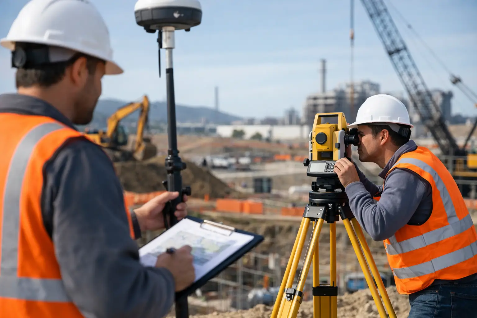
    A gridline that is 20 mm out may look insignificant on a busy site. By the time steelwork, drainage runs, precast units or façade elements rely on it, that small error can become a costly programme and coordination issue. This guide to construction setting out explains how to establish, transfer and verify design positions with the control needed for reliable construction delivery.

    Construction setting out is not simply marking points on the ground. It is the process of translating approved design information into physical positions, levels, lines and reference marks that site teams can build from. The quality of that process affects excavation, foundations, structural alignment, services installation and final as-built records.

    What construction setting out must achieve

    The objective is to provide unambiguous, traceable site information at the required accuracy. A setting-out surveyor must confirm where an element is to be built, at what level, relative to which coordinate system, and with what tolerances. Those requirements vary considerably between a bulk earthworks operation and a reinforced concrete frame.

    Typical setting-out tasks include establishing site control; positioning building corners, gridlines and pile locations; transferring formation and finished floor levels; setting drainage alignments and gradients; and checking completed work against the design. The same survey control may also support machine control, volume calculations, progress reporting and as-built surveys.

    Accuracy should be defined by the work being undertaken, not by a blanket specification. Earthworks can often be managed at centimetre-level tolerance, while steelwork, holding-down bolts and structural interfaces may require millimetre-level precision. Selecting an instrument and workflow without considering those tolerances is a common cause of avoidable rework.

    Start with reliable survey control

    Every dependable setting-out operation begins with a control network. This consists of stable, well-documented points with known coordinates and levels, tied to the project’s approved datum and coordinate reference system. It gives every trade a common spatial reference and prevents individual teams from working to inconsistent local assumptions.

    Control points should be located outside likely excavation areas, traffic routes and zones where they may be disturbed by plant. They need clear physical marking, protection and a record of coordinates, descriptions, photographs and date of verification. A point painted on a kerb or timber profile may be convenient, but it is not automatically suitable as primary control.

    A closed traverse, GNSS observations or a combination of both may be used to establish control. The right approach depends on site scale, obstructions, required precision and the relationship between the design grid and national coordinates. GNSS with RTK corrections is efficient for establishing and checking open-site control, but a total station generally provides the tighter relative precision needed for detailed structural set-out.

    Levels require equal care. A project benchmark should be checked against the approved vertical datum before work begins. On sites where precise levels matter, differential levelling remains a highly reliable method for transferring height. GNSS-derived elevations can be useful operationally, but they depend on the correct geoid model, correction service and coordinate configuration.

    Prepare the design data before going to site

    Most setting-out errors originate before the surveyor switches on an instrument. Drawings, models and coordinate schedules must be reviewed for completeness, consistency and version control. A coordinate list that has been issued from an outdated model is still wrong, even if it is set out perfectly.

    Confirm the drawing revision, units, coordinate system, grid orientation and level datum. Check whether coordinates are expressed in a local engineering grid, the British National Grid, or a project-specific transformation. A rotation, scale factor or false origin that has not been applied correctly can shift every point on site.

    For model-based workflows, extract only the information required for the activity. Grid intersections, pile centres, kerb lines, formation surfaces, drainage centre lines and offset points should be clearly named and checked against the source drawing. Avoid cluttering a field controller with unfiltered model geometry, particularly where several design options or superseded layers are present.

    Before mobilisation, carry out independent calculations on a sample of critical points. Comparing gridline distances, diagonals, levels and offsets against the approved drawings is a practical way to identify data-export mistakes. This check should be documented, especially where the works involve high-value structural elements.

    Choosing the right equipment for the task

    A robotic total station remains the primary instrument for many detailed setting-out applications. It provides high angular and distance precision, can work to a local control network and is well suited to gridlines, foundations, columns, retaining walls and structural interfaces. One-person robotic workflows can also improve productivity where access and line of sight are available.

    GNSS RTK rovers are highly effective for initial control, earthworks, road alignments, utilities routes and rapid checks over larger areas. They reduce the need for line of sight between points, but performance can be affected by tree cover, buildings, multipath and limited sky visibility. They are not a substitute for a total station where tight relative tolerances apply.

    Digital levels are appropriate when transferring precise heights, while laser levels can provide a quick reference for routine construction activities. Terrestrial LiDAR scanning and drone photogrammetry add value by capturing existing conditions, monitoring earthworks, documenting progress and producing detailed as-built point clouds. These technologies complement conventional setting out rather than replacing the need for verified control.

    The best choice is often a combined workflow: GNSS for efficient site-wide control and open-area work, total station measurement for precise placement, and scanning for verification and record capture.

    A practical construction setting-out workflow

    Once control and design data are approved, the field process should follow a disciplined sequence. Set up over a known point or use a known occupied station, then orient the instrument to one or more backsights. Check the instrument height, prism height and target settings before measuring any design point.

    A strong orientation check measures an additional known control point that was not used as the backsight. If the residual exceeds the project tolerance, stop and investigate rather than proceeding with set-out. The cause may be an incorrect point selection, a disturbed control mark, poor prism centring or an error in the coordinate file.

    Set out critical locations using a method appropriate to the construction stage. For a building footprint, establish primary gridline intersections and offsets that remain available after excavation. For piles, mark centres with clear identifiers and provide offset references where pile caps or ground conditions may obscure the original mark. For drainage, stake centre lines, changes of direction, manhole positions and formation levels, while ensuring gradient calculations are checked independently.

    Site marks must be understandable to the people building from them. A precise point is of limited value if the marking convention is unclear. Use agreed labels, paint colours, nails, witness marks or profiles, and record whether a mark represents a centre line, face of wall, finished level, excavation limit or offset. Communication with the site engineer and foreman is part of accurate delivery.

    Verification is where risk is controlled

    Setting out should never rely on a single observation for critical work. Independent checks provide the confidence that the right point has been placed in the right position from the right control.

    For structural work, verify gridline spacing, diagonals, offsets and levels before concrete is poured or steel is fixed. Where possible, use a second setup, a different control route or a second instrument operator. A check performed from the same station with the same incorrect orientation is not genuinely independent.

    As-built measurement is equally important. Capture completed elements before they are concealed, including foundations, drainage, service trenches and reinforcement interfaces where required. Compare measured coordinates and levels with design tolerances, then issue clear records showing any deviations and whether they have been accepted.

    LiDAR or photogrammetric capture can provide a broader verification record for complex or fast-moving sites. Point clouds are particularly useful for checking excavation profiles, concrete surfaces, stockpiles and installed assets. Their value depends on survey-grade registration and well-managed control, not simply on the volume of data collected.

    Common setting-out failures and how to avoid them

    The most damaging errors are often routine: working from a superseded drawing, assuming a control point has not moved, entering the wrong prism height, or mixing local and national coordinate systems. These issues are preventable through documented checks and clear responsibility for data release.

    Poor site conditions also matter. Heat shimmer, rain, vibration, restricted line of sight and unstable ground can affect measurements and instrument setups. Plan work around conditions where practical, use forced centring for repeat setups, and check control more frequently on active or heavily trafficked sites.

    Do not treat tolerance as an afterthought. Agree it before setting out begins, record the required standard in the survey method statement, and escalate discrepancies promptly. A small design conflict found before installation is a coordination task. The same conflict found after construction may become a commercial dispute.

    For projects that need an integrated survey workflow, LiDAR Tech UK can support professional teams with GNSS, robotic surveying, LiDAR capture and practical technical guidance matched to the accuracy and output requirements of the works.

    The most useful setting-out record is one that allows the next person on site to understand exactly what was established, checked and handed over. When control, design data and verification are treated as one connected process, site teams can build with greater confidence and far fewer surprises.

  • Best RTK Rovers Comparison for UK Surveyors

    Best RTK Rovers Comparison for UK Surveyors

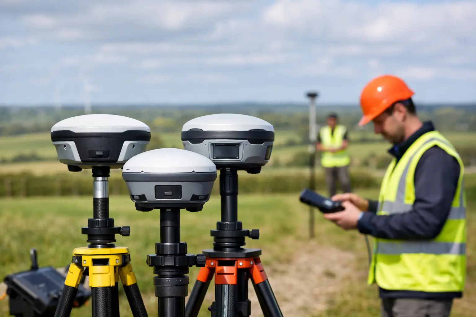
    A best RTK rovers comparison for a UK survey team should start with the work, not the specification sheet. A rover that performs well for setting out on an open construction site may be a poor fit for utility surveys beneath tree cover, while a lower-cost unit can become expensive if it creates correction, data-export or support issues in the field.

    For professional users, the best choice is usually the rover that delivers repeatable centimetre-level positions within an established workflow. That means assessing GNSS performance, correction reliability, controller software, field durability and the support available when a crew needs an answer quickly.

    What separates the best RTK rovers?

    An RTK rover receives satellite signals and applies real-time corrections from a local base station or correction network. In suitable conditions, this enables survey-grade positioning for topographic work, site control, setting out, as-built surveys, GIS capture and machine-control support.

    The headline accuracy figure matters, but it is only one part of the decision. Most professional rovers quote horizontal accuracy in millimetres plus parts per million when operating with a fixed RTK solution. In practice, the more useful question is how consistently the receiver achieves and retains that fixed solution around buildings, under partial canopy and near machinery.

    A capable rover should also fit the software and deliverables used by the business. If field crews need CAD-ready points, coded linework, stake-out reports or asset attributes, the controller and office workflow deserve the same scrutiny as the GNSS receiver.

    Best RTK rovers comparison: the key buying criteria

    Satellite tracking and signal resilience

    Modern professional GNSS rovers track multiple constellations, typically GPS, Galileo, GLONASS and BeiDou, across multiple frequencies. More tracked signals can improve solution availability, particularly where the sky view is restricted. However, multi-constellation capability does not remove the effects of dense canopy, reflective surfaces or poor correction coverage.

    For urban, infrastructure and woodland work, look beyond the advertised channel count. Ask for a demonstration in conditions that resemble the difficult parts of your sites. Observe time to fixed solution, how the unit recovers after obstruction, and whether it reports solution status clearly enough for the operator to make sound decisions.

    Correction methods and network access

    A rover is only as useful as its correction source. UK users commonly work from an NTRIP correction service through a SIM-enabled controller or receiver, although a local base and rover arrangement remains valuable on remote sites or where independent control is required.

    Network RTK reduces setup time and is often the most practical option for mobile survey teams. It depends on mobile coverage, subscription access and a correctly configured coordinate reference system. A base-rover kit gives greater control and can operate without internet coverage, but it adds setup, radio planning and base-coordinate responsibilities.

    Before purchasing, confirm the correction services available across your operating area and test the intended SIM provider on known weak-coverage sites. For critical work, a workflow with a secondary correction option is sensible.

    Field software and data flow

    The receiver may be the visible part of the kit, but field software dictates much of its daily value. A strong system should make it straightforward to create jobs, select the right coordinate system, import design data, code observations, stake out points and lines, and export files in formats accepted by CAD, GIS or machine-control platforms.

    Construction teams often prioritise fast stake-out, cut-and-fill information and clear reports. Survey practices may need survey coding, linework collection, raw observation storage and reliable integration with existing office software. Utilities and asset managers may place greater value on configurable forms, photographs and attribute capture.

    Do not assume that every controller package supports each workflow in the same way. Request a walkthrough using a representative drawing, coordinate file or asset form. This exposes avoidable friction before equipment reaches site.

    Tilt compensation

    Tilt-compensated rovers allow the pole to be held away from vertical while calculating the antenna position. This can speed up work around walls, vehicles, boundaries and inaccessible points, and it can reduce the need to level the pole at every observation.

    The trade-off is operational discipline. Tilt compensation must be correctly calibrated and used within the manufacturer’s stated limits. It does not make poor satellite geometry, multipath or an unstable pole acceptable. For control points and high-consequence setting-out tasks, many teams still adopt a more cautious observation procedure, including checks on solution quality and repeat measurements.

    Build quality, battery and connectivity

    A rover intended for daily commercial work should withstand rain, dust, vibration and repeated transport between sites. Check the stated ingress protection rating, operating temperature range, battery arrangement and warranty terms. A removable battery can be useful for long shifts, while an integrated battery can simplify handling but requires a charging plan.

    Connectivity also deserves attention. Bluetooth reliability between receiver and controller, internal modem support, radio capability, Wi-Fi configuration and USB data transfer all affect field productivity. Small delays at the start of every job become costly over a year of deployment.

    Comparing rover types for UK applications

    Entry-level professional rovers are suited to teams moving from manual tape-and-offset methods, basic GPS or subcontracted setting-out. They can offer a strong return for open-sky topographic surveys, volume calculations, agricultural measurement and routine construction layout. The limitation is usually not basic accuracy, but lower resilience, fewer workflow features or a more limited support package.

    Mid-range survey rovers are often the strongest commercial choice for contractors, consultants and multi-disciplinary survey teams. They typically combine multi-frequency tracking, tilt capability, mobile corrections and capable field software. This category is appropriate where one team needs to cover topo, as-built, stake-out and asset capture without carrying several systems.

    Premium survey-grade systems are justified where complex sites, demanding client specifications, established survey workflows and high utilisation make downtime costly. Their value may come from advanced signal handling, mature controller software, integration with total stations or machine-control environments, and an extensive support ecosystem. They should be assessed on total operational value rather than receiver price alone.

    A separate category is the compact GIS-focused rover. These are designed around efficient asset capture and attribute collection, often with mobile mapping applications. They are useful for councils, environmental teams and utilities, but may not replace a full survey rover where detailed setting out, survey coding or formal deliverables are required.

    Accuracy is a process, not a claim

    No RTK receiver should be treated as a substitute for survey control and verification. Good practice begins with the correct project coordinate system and a known control point wherever possible. The operator should check that the correction stream, antenna height, pole height and solution status are correct before collecting production data.

    On a well-managed project, crews carry out check shots during the day, repeat critical observations and record sufficient information to demonstrate how points were established. This is particularly important where data will support design decisions, quantities, legal boundaries or safety-critical construction activity.

    When comparing equipment, ask suppliers how the system handles quality indicators, residuals, raw data logging and re-observation. A clear audit trail is more valuable than a promising accuracy figure that cannot be verified later.

    Whole-life cost matters more than purchase price

    The lowest-priced rover can be a sound investment when it matches the task and the operator is competent. It becomes a false economy when crews lose time configuring corrections, struggle with exports, or wait days for technical support during an active job.

    Budget for the complete working system: rover, controller, pole, bracket, batteries, charger, protective case, correction subscription, software licences, training and any required base station. Also account for calibration procedures, firmware updates, repair turnaround and replacement equipment availability.

    For many organisations, the most valuable supplier contribution is implementation. A proper handover should cover coordinate systems, correction setup, field workflows, quality checks and data export. LiDAR Tech UK supports this broader approach, helping teams align GNSS equipment with their real survey and mapping requirements rather than simply supplying a receiver.

    How to make a confident selection

    Start by defining the outputs your team must produce and the environments where they work. Then shortlist systems that meet those requirements, arrange a practical demonstration and test them against a familiar workflow. Compare fixed-solution reliability, time on task, exported data quality and ease of use for the people who will operate the equipment every day.

    The right RTK rover should make accurate spatial data easier to capture, check and deliver. A careful field trial will show whether it can do that on your sites, with your corrections, and within the standards your clients expect.

  • Best LiDAR Scanners Comparison for UK Surveys

    Best LiDAR Scanners Comparison for UK Surveys

    A scanner that produces an impressive point cloud in a showroom can still be the wrong choice for a live construction site, rail corridor or heritage building. The most useful best lidar scanners comparison starts with the deliverable: the accuracy required, the environment being captured, the distance to cover and how quickly the data must reach CAD, BIM or asset-management systems.

    For UK survey, engineering and asset teams, LiDAR selection is rarely a simple question of range or point density. A faster capture method may reduce time on site, but it must also provide enough control, registration confidence and usable detail for the intended decision. The right scanner is the one that improves the whole workflow, rather than merely collecting data quickly.

    Best LiDAR scanners comparison: choose by workflow

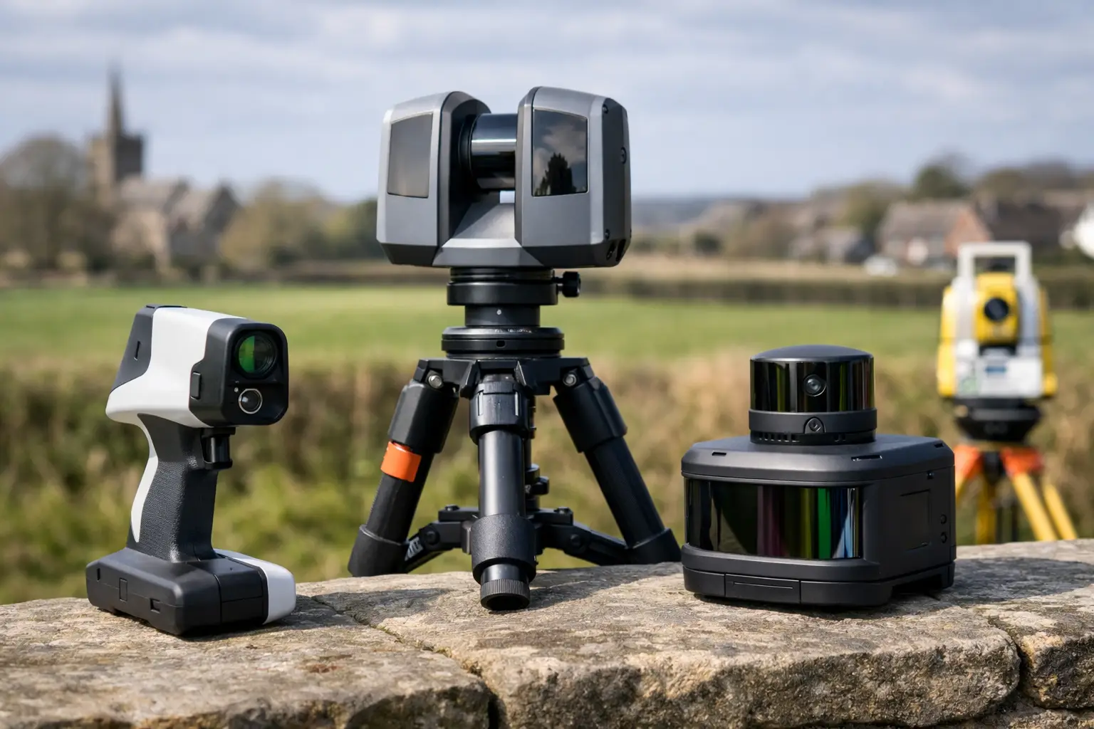
    Professional LiDAR systems generally fall into four practical categories: handheld SLAM scanners, backpack or vehicle-mounted mobile mapping scanners, static terrestrial laser scanners and drone-mounted LiDAR systems. Each solves a different field problem.

    | Scanner type | Best suited to | Main advantage | Key consideration | |—|—|—|—| | Handheld SLAM LiDAR | Buildings, plant rooms, construction progress and confined spaces | Rapid, mobile capture with minimal set-up | Accuracy and drift management depend on survey control and capture route | | Backpack or mobile mapping LiDAR | Roads, rail, estates, forestry and large external sites | Efficient coverage across long corridors or wide areas | Requires careful trajectory planning and GNSS performance where used outdoors | | Static terrestrial laser scanner | High-detail surveys, deformation work, façades and complex geometry | Strong measurement control and detailed stationary scans | Multiple set-ups can increase site time and registration effort | | Drone LiDAR | Difficult terrain, roofs, quarries, utilities routes and large land areas | Safe, efficient aerial coverage | Flight permissions, vegetation penetration needs and ground control remain critical |

    There is no universal winner. A static scanner can be the better investment where millimetre-level detail and repeatable control matter more than speed. A handheld SLAM system can be more productive where access, programme pressure and complex internal routes are the limiting factors. In many projects, combining methods produces the strongest result.

    Handheld SLAM LiDAR: speed where set-up time is the problem

    Handheld LiDAR scanners use simultaneous localisation and mapping, commonly known as SLAM, to build a point cloud while the operator walks through an environment. They are particularly effective for internal surveys, multistorey buildings, industrial facilities, tunnels and construction projects where traditional static set-ups would interrupt work or take several days.

    The practical advantage is not simply that the scanner is portable. It is that the operator can capture stairwells, corridors, plant areas and external transitions in one continuous workflow. This reduces blind spots caused by static scanner positions and makes frequent progress capture commercially realistic.

    FJDynamics Trion systems are designed for this type of mobile reality capture. They offer a practical route into survey-grade SLAM workflows for teams that need to collect spatial data efficiently without carrying out a full static scan at every location. However, the scanner should not be assessed on headline specifications alone. Review how it handles loop closures, control points, challenging surfaces, low-feature corridors and processing within the software workflow your team uses.

    Handheld SLAM is an excellent fit for as-built verification, MEP coordination, measured building surveys, stockpile environments and rapid site documentation. It is less suitable as a direct replacement for static terrestrial scanning where a client requires tightly controlled, independently verified measurements across a large or high-precision survey network.

    What to check before buying a handheld scanner

    Ask for demonstrated results from a site similar to your own. A warehouse with repetitive racking, a long corridor with few visual features and a busy plant room can each challenge a SLAM workflow differently. Also establish whether you need surveyed control targets, GNSS positioning outdoors or both.

    Processing time matters as much as capture time. A system that produces a clean, registered point cloud with straightforward export to common design and modelling packages can save considerably more labour than one that requires extended manual correction after every survey.

    Backpack and mobile mapping LiDAR: cover more ground per shift

    Backpack and vehicle-based systems are intended for larger areas and longer routes. Typical applications include highways, rail estates, campuses, industrial facilities, forestry tracks, urban streets and utility corridors. The value lies in collecting dense spatial information while moving continuously, rather than stopping repeatedly for individual scanner positions.

    These systems often benefit from a combination of LiDAR, inertial measurement, GNSS/RTK positioning and SLAM. Where satellite visibility is good, GNSS can strengthen georeferencing and reduce the need for extensive downstream adjustment. Under tree canopy, beside tall buildings or inside structures, the system must rely more heavily on its inertial and SLAM performance.

    This is where operational planning becomes decisive. A poor route with no revisits, limited control or interrupted GNSS conditions can create a point cloud that looks complete but does not meet positional requirements. Surveyors should plan loops, establish check points and define a clear coordinate reference strategy before capture begins.

    For organisations maintaining assets across extensive sites, mobile mapping can make repeat surveys more affordable. It is particularly valuable when the objective is an up-to-date, measurable digital record rather than a small number of isolated measurements. The trade-off is that hardware choice, mounting method, correction service and processing standards need to work together from the outset.

    Static terrestrial scanners: where control and detail take priority

    Static terrestrial laser scanners remain the benchmark for many high-detail measured surveys. The scanner is positioned on a tripod, captures from a fixed location and is moved through a planned network of set-ups. This method is proven for architecture, structural surveys, façades, industrial installations, heritage records and situations where precise geometry must be evidenced.

    The main strength is control. With suitable target placement, survey control and registration procedures, static scanning provides dependable datasets for demanding design, conservation and engineering use. It also handles fine detail at a stand-off distance well, which can matter when access is restricted or objects cannot be approached safely.

    Its limitation is field productivity. Complex sites may require numerous scan positions to avoid occlusions, and each position needs time to establish, capture and register. For a small, detailed room this may be entirely appropriate. For a 20,000-square-metre operational building requiring weekly progress data, a mobile workflow may provide a better commercial balance.

    The decision should therefore be based on the tolerance of the final deliverable. If drawings, clash detection or asset models need highly controlled geometry, static scanning is often justified. If the goal is rapid condition recording, space planning or progress visualisation, handheld LiDAR may be more efficient.

    Drone LiDAR: a separate answer to inaccessible terrain

    Drone LiDAR belongs in a best LiDAR scanners comparison because it changes what can be captured safely, not because it replaces ground scanning. Aerial platforms are well suited to embankments, quarries, roof structures, woodland, transmission routes and broad infrastructure sites where walking the full area is slow, unsafe or impractical.

    LiDAR can often capture terrain through gaps in vegetation more effectively than photogrammetry, making it valuable for topographic modelling and corridor work. Yet vegetation density, flight height, scan angle, platform stability and ground control all affect the result. A drone LiDAR survey requires competent flight planning, appropriate permissions and a clear understanding of the required ground classification outputs.

    For detailed building interiors, equipment surveys and below-canopy asset checks, ground-based LiDAR remains essential. The most productive projects may use aerial LiDAR for the wider context and mobile or static scanning for detailed verification at ground level.

    The specification questions that prevent expensive mistakes

    Range, points per second and stated accuracy are useful comparison figures, but they do not tell the whole story. Ask suppliers how the published accuracy is measured and whether it refers to sensor performance, relative point-cloud precision or final georeferenced survey accuracy. These are not interchangeable.

    Consider the working environment. Reflective surfaces, glazing, black materials, rain, dust and direct sunlight can affect capture quality. So can featureless areas, moving people or vehicles, and repetitive structures. A practical demonstration should reflect these conditions rather than an idealised test space.

    Data compatibility deserves equal attention. Confirm the point-cloud formats, registration tools, classification options and exports available for your existing CAD, BIM, GIS or asset-management workflow. If the scanner requires a specialist processing route, ensure the team has the training, computing capacity and support to use it consistently.

    Finally, compare the support model. Professional LiDAR is an operational system, not just a purchase. Training, field set-up advice, software guidance, technical response times and access to processing expertise all influence whether the equipment delivers a return. LiDAR Tech UK supports organisations that need this wider implementation capability, from equipment selection through to survey delivery and usable data outputs.

    Build the comparison around the decision you need to make

    Before requesting quotations, define the required coordinate system, survey tolerance, deliverables, typical site size and target turnaround. Then test candidate scanners against a representative job. Capture the same area, process it using the proposed workflow and compare not only the point clouds, but also field time, office time, missing detail and confidence against known checks.

    The best choice is often the system that gives your team sufficient accuracy with the least operational friction. A well-supported scanner matched to the job can reduce site exposure, shorten programmes and produce data that design and asset teams can act on with confidence.

  • How to Reduce Survey Rework on Complex Sites

    How to Reduce Survey Rework on Complex Sites

    A return visit to site is rarely just an inconvenience. It can delay design decisions, hold up setting-out, increase traffic management costs and leave a project team working from data it cannot fully trust. Knowing how to reduce survey rework starts with treating capture, control, processing and deliverables as one connected workflow rather than separate tasks.

    For UK survey, engineering and asset-management teams, the goal is not simply to collect more data. It is to collect defensible data that meets the agreed specification first time, with clear traceability from site control through to CAD, BIM or GIS output.

    Why survey rework happens

    Most rework is created before the survey team reaches site. An unclear brief may omit the required coordinate reference system, tolerance, datum, deliverable format or extent of coverage. The field team then makes reasonable assumptions, but those assumptions may not match the requirements of the designer, client or downstream contractor.

    Control errors are another common cause. A well-executed scan or drone flight cannot compensate for incorrect control coordinates, an unsuitable transformation, poor GNSS correction coverage or an unrecognised level datum issue. Problems may not become visible until data is overlaid with an existing design model, by which stage mobilisation is needed again.

    There is also a practical issue of visibility. Traditional point-based methods can leave gaps where access is restricted, vegetation obscures features, traffic limits working time or complex structures contain numerous hidden surfaces. The data may be technically accurate where it exists, but insufficient for the decisions that follow.

    The answer is not to use every available technology on every project. It is to select a method that provides the required accuracy, completeness and verification within the actual constraints of the site.

    How to reduce survey rework before mobilisation

    Start with a survey brief that can be checked, not interpreted. The brief should identify the purpose of the survey, required accuracy, site limits, control basis, exclusions, linework or model requirements, and the software environment in which the data will be used. If the end user needs breaklines, classified point clouds, floor plans, mesh models or CAD-ready drawings, state this at the outset.

    It is equally useful to agree what “complete” means. For a highway corridor, that may include all visible drainage assets, kerb lines, utility indications and tie-ins beyond the proposed works. For a building survey, it may mean every plant area, soffit, service route and inaccessible façade elevation needed for design. Completeness is project-specific, so it should be defined before capture rather than debated during data processing.

    A short pre-start review should confirm the following five points:

    • the coordinate system, geoid model and vertical datum;
    • available control points and how they will be verified;
    • required absolute and relative accuracy;
    • site access, hazards, closures and working restrictions; and
    • the final file formats, naming conventions and acceptance checks.

    This review is particularly important where several organisations contribute to the same scheme. A contractor may be using a local grid, while a design team works in British National Grid and an asset owner holds records on a different historical datum. Establishing the transformation route early is faster than trying to reconcile datasets after construction has begun.

    Build control you can defend

    Reliable control is the foundation of repeatable survey data. Whether the work uses a GNSS rover, total station, mobile LiDAR system or drone, control should be independently checked rather than assumed correct because it appears in a drawing or legacy file.

    For GNSS-based work, assess correction service availability and the conditions likely to affect positional quality. Dense urban areas, tree cover, steep cuttings and proximity to structures can reduce satellite visibility or introduce multipath effects. In these environments, a fixed RTK solution alone should not be treated as proof that the final position meets the specification.

    Use check points that are separate from the points used to constrain or register the dataset. Comparing measured values against independent checks creates an audit trail and exposes systematic issues early. If the tolerance is tight, repeat observations at different times or use a complementary method to verify critical features.

    The trade-off is straightforward: additional control takes time at the beginning of a job. However, that time is usually modest compared with the cost of revisiting a live construction site, arranging possession access or revising issued drawings.

    Capture enough context, not just the requested feature

    Survey teams are often asked to capture a defined asset, boundary or structure. Rework occurs when the design team later requires the surrounding context to understand drainage falls, clearance, connections, access routes or construction interfaces.

    LiDAR and photogrammetry are valuable here because they can capture dense spatial context efficiently. A terrestrial or mobile LiDAR survey can record complex geometry and surfaces that would be slow to represent with individual observations. Enterprise drone surveys can extend coverage across larger or unsafe areas, subject to suitable ground control, airspace planning and site conditions.

    Neither method removes the need for survey judgement. Reflective surfaces, water, moving vehicles, glass, dense vegetation and occluded areas all require a considered capture plan. A point cloud may look complete in a viewer while still containing shadow areas or unreliable returns. Field staff should inspect coverage during the survey, not rely solely on post-processing to reveal omissions.

    For complex sites, work to planned routes, stations or flight blocks and record what has been completed. This makes it easier to identify gaps while access remains available. It also protects the project when site conditions change between visits.

    Validate in the field and again in the office

    The strongest field-to-office workflow has two quality gates. The first takes place on site: check control, coverage, instrument status and a sample of critical dimensions before demobilising. The second takes place during processing: verify registration quality, compare independent check points, inspect point-cloud density and review outputs against the agreed brief.

    Do not wait until drawings are nearly complete to perform these checks. Early validation allows a team to identify a missing elevation, weak registration area or inconsistent datum while a short supplementary visit is still practical. It also prevents processing effort being spent on data that will later be rejected.

    A useful approach is to define acceptance criteria before fieldwork begins. For example, a project may require specified residuals on survey control, an agreed maximum deviation at check points, full coverage of named assets and a clear record of areas that could not be observed. The exact values depend on the survey class and design use, but the principle is consistent: quality should be measured against known criteria, not assessed by appearance alone.

    Standardise the field-to-office handover

    A technically sound survey can still create rework if files arrive with ambiguous names, missing raw data, inconsistent layers or no record of processing settings. Standardisation makes work easier to check, easier to repeat and less dependent on one individual’s knowledge.

    Create a consistent project structure for raw observations, control records, images, point clouds, processed data and issued deliverables. Include a concise survey report that states equipment used, coordinate reference system, control methodology, checks completed, known limitations and achieved accuracy. This is not administrative padding. It gives designers and asset owners the information they need to use the data correctly.

    Where point clouds are delivered, agree practical requirements such as format, classification, decimation level, clipping boundary and whether registration reports are required. A high-density dataset is not always the best deliverable if the client lacks the software or computing capacity to handle it. In some cases, a clean CAD drawing, mesh, orthomosaic or extracted asset schedule is more useful alongside the source data.

    Choose technology around the risk, not the trend

    The best equipment choice depends on the site and required outcome. GNSS/RTK rovers are highly efficient for open environments and control establishment. LiDAR scanners are well suited to dense, complex or inaccessible geometry. Drones can reduce exposure and accelerate coverage across large areas. Total stations remain essential where high precision and controlled observations are required.

    In many projects, the most reliable answer is a combined workflow. GNSS can establish and verify control, LiDAR can capture detailed geometry, and targeted total-station observations can confirm critical points that are difficult to interpret from a point cloud. This approach may involve more planning, but it reduces reliance on a single source of evidence.

    LiDAR Tech UK supports organisations with the equipment, implementation guidance and data-capture capability needed to build these workflows around real site conditions rather than generic specifications.

    Make rework visible and improve the next job

    Finally, record why a return visit occurred. Was it a missing feature, unclear brief, control discrepancy, access restriction, software compatibility issue or an output that did not meet the intended use? Tracking these causes turns isolated problems into measurable process improvements.

    The most effective survey teams do not aim for zero questions during delivery. They aim to surface the right questions before mobilisation, verify the answers while still on site, and issue data that can stand up to design, construction and asset-management scrutiny.

  • What Accuracy Does RTK Deliver in Surveying?

    What Accuracy Does RTK Deliver in Surveying?

    A GNSS receiver showing a fixed RTK solution can transform a day’s work. But what accuracy does RTK deliver when the results need to stand up in a setting-out file, an as-built survey, a volume calculation or an asset record? For most professional field applications, correctly configured RTK can achieve centimetre-level absolute positioning – commonly around 8 mm horizontal and 15 mm vertical, plus a parts-per-million distance component, under favourable conditions.

    That specification is highly capable, but it is not a blanket guarantee of 1 cm everywhere on every site. RTK accuracy depends on the correction source, satellite visibility, baseline length, coordinate reference system, antenna setup and field verification. Understanding those dependencies is what turns a capable rover into a dependable survey workflow.

    What Accuracy Does RTK Deliver in Practice?

    Real-time kinematic positioning uses carrier-phase measurements from GNSS satellites and correction data from a base station or network. The rover compares its observations with the correction source, resolves the integer ambiguities and reports a fixed solution. Once fixed, it can deliver positions far more precise than standalone GNSS.

    A realistic expectation for an open-sky site, with a quality receiver and a fixed solution, is approximately 1-2 cm horizontal accuracy and 1.5-3 cm vertical accuracy at the measured point. The vertical component is normally less precise than the horizontal component. This matters when surveying drainage, carriageway levels, earthworks platforms or any feature where reduced level tolerances drive the decision.

    Manufacturers often express performance as a figure such as 8 mm + 1 ppm horizontally and 15 mm + 1 ppm vertically. The first figure is the base measurement uncertainty. The ppm element increases with separation from the correction source. At a 10 km baseline, 1 ppm adds 10 mm. Network RTK reduces the practical effect of longer distances by modelling atmospheric errors across multiple reference stations, but conditions and service quality still matter.

    It is also essential to separate precision from accuracy. A rover may repeat very closely around the same incorrect coordinate if the wrong coordinate system, transformation or antenna height has been entered. Repeatability is useful, but it is not proof that the data is correctly tied to the required project datum.

    The Difference Between a Fixed and Float Solution

    The status shown by the controller is not a minor detail. A fixed solution means the receiver has resolved the carrier-phase ambiguities with sufficient confidence. This is the condition required for centimetre-level work. A float solution has not completed that resolution and can be decimetres out, occasionally more.

    Do not treat a float coordinate as an RTK survey observation simply because corrections are being received. Wait for fixed status, review the reported horizontal and vertical precision, and re-observe critical points. If the receiver repeatedly drops from fixed to float, the underlying cause needs attention rather than a workaround.

    Typical causes include tree canopy, building façades, steelwork, parked plant, overhead obstructions and poor mobile-data coverage. These can block satellites, reflect signals and interrupt correction delivery. A good receiver cannot remove the physical limitations of the sky view.

    Why Site Conditions Change the Result

    The advertised RTK figure is normally established in controlled, open-sky conditions. Construction and infrastructure environments are rarely that simple. Multipath is one of the most common sources of poor performance: satellite signals reflect from walls, glass, water, metal or machinery before reaching the antenna. The receiver may still report fixed, yet the observation can be biased.

    Dense woodland creates another challenge. A rover may maintain a solution under light canopy, but satellite geometry and signal quality can deteriorate rapidly as foliage, branches and terrain obstruct the horizon. In forestry, boundary work or corridor mapping, it is often sensible to combine RTK with total station observations, post-processed GNSS or LiDAR and photogrammetry workflows, depending on the required deliverable.

    Satellite geometry also affects confidence. A receiver tracking many satellites does not automatically have an ideal geometry. Satellites concentrated in one area of the sky provide weaker geometric strength than a well-distributed constellation. Checking PDOP, signal quality and solution age helps the operator recognise when a measurement deserves another observation.

    Coordinate Systems Matter as Much as GNSS Performance

    For UK projects, a centimetre-level measurement in the wrong reference frame is still wrong. RTK corrections may be supplied in ETRS89 or another GNSS reference frame, while project drawings, cadastral information and engineering models may use OSGB36 National Grid. Heights introduce a separate issue: ellipsoidal GNSS height is not the same as orthometric height relative to Ordnance Datum Newlyn.

    The controller, correction service and processing software must use a consistent transformation and geoid model. A mismatch can create offsets that are far larger than the rover’s stated RTK precision. These errors can be systematic, meaning every surveyed point appears credible but is displaced by the same amount.

    Before starting work, establish the project coordinate system and vertical datum, then confirm how those are configured in the rover. On controlled sites, check known control points before and during the survey. If the project control and RTK observations disagree, do not force the data to fit without identifying whether the cause is a local grid, control issue, transformation setting or antenna-height error.

    Antenna Height Is a Small Input With Large Consequences

    RTK measures the position of the antenna phase centre, not the ground point, kerb edge or prism point of interest. The controller applies the entered antenna or pole height to calculate the final coordinate. A 20 mm height-entry error produces approximately a 20 mm error in the reported level.

    Use a stable pole, a calibrated bubble or tilt-compensation system, and the correct measurement method specified by the equipment. Tilt compensation can improve productivity when capturing detail, but it does not make poor control, multipath or a wrong antenna height disappear. For critical level work, a levelled pole and independent check remain good practice.

    Setting Out, Topographic Survey and Machine Control

    RTK is particularly effective where the tolerance aligns with centimetre-level positioning and productivity matters. Topographic surveys, utility asset capture, stockpile measurement, agricultural guidance, preliminary site models and many construction setting-out tasks are strong applications. It allows a single operator to capture or stake out large numbers of points quickly without establishing line of sight between instruments.

    The correct tolerance should always determine the method. If a task requires a few millimetres, such as precision structural alignment, settlement monitoring or certain rail and industrial installation activities, RTK alone may not be sufficient. A total station, digital level, static GNSS or a combined control approach may be more appropriate.

    For machine control, the practical question is not merely the rover’s best-case accuracy. It is the accuracy of the entire chain: design model, site calibration, base or correction network, machine antenna configuration, sensor calibration and regular checks against physical control. A 10 mm rover specification cannot compensate for an outdated design surface or a site calibration with a 30 mm residual.

    A Field Procedure That Protects Accuracy

    Reliable RTK work is built on routine checks rather than faith in a status icon. At the start of a shift, occupy at least one known point and compare the measured coordinate with the expected value. Repeat the check after moving between work areas, following a correction outage, after changing coordinate settings or when operating close to obstructions.

    For important surveyed features, take independent repeat observations. Reoccupation after a short interval, ideally with a different satellite geometry, is a practical way to reveal a questionable result. Record solution status, precision values, correction source, antenna height and any site limitations in the field notes. These details provide a useful audit trail if the data is later queried.

    Quality control should continue in the office. Review outliers, check levels against known control and confirm that the exported data uses the specified coordinate reference system. Where the results feed CAD, BIM, GIS or an engineering model, clear naming and coding reduce the risk of a correct coordinate becoming an incorrect deliverable.

    Choosing the Right RTK Setup

    A local base and rover can give excellent results where the base is established on verified control and the project needs an independent site reference. It also avoids dependence on mobile coverage for local radio-based corrections. However, it requires setup, radio planning and confidence in the base coordinate.

    Network RTK is efficient for mobile survey teams working across multiple locations. It removes the need to establish a base each day, provided the correction service is available and the rover has reliable data connectivity. For many UK survey and construction applications, it is the practical default. The decision should be based on control requirements, geography, communications and the consequence of downtime – not only on subscription cost.

    LiDAR Tech UK can help assess the appropriate rover, correction method and field-to-office workflow for the accuracy your project actually requires. The most valuable RTK result is not the smallest figure on a specification sheet; it is a verified coordinate that lets the next team make the right decision with confidence.

  • A Professional Guide to LiDAR Data Capture

    A Professional Guide to LiDAR Data Capture

    A point cloud is only as valuable as the decisions made before the scanner is switched on. This guide to LiDAR data capture is intended for UK survey, construction and asset teams that need reliable, usable spatial data rather than a large file that creates more work in the office. The objective is to define the required output, select a capture method that suits the site, establish dependable control and maintain quality checks from fieldwork through to delivery.

    Start with the required deliverable

    LiDAR capture should begin with the question: what will the data be used for? A topographic survey, volume calculation, BIM model, highway corridor, asset inventory and heritage record each require a different balance of accuracy, density, coverage and classification.

    For example, a contractor checking cut and fill may need a georeferenced surface model delivered quickly. An engineering team producing a detailed design model may require more stringent control, defined feature extraction and CAD-ready linework. A facilities manager documenting plant rooms may prioritise complete coverage around equipment and clear imagery to support identification.

    Set the specification before mobilisation. It should identify the coordinate reference system, vertical datum, required accuracy, point density, deliverable formats, exclusions and tolerances. Agree whether the client needs raw point clouds, registered scans, classified data, a digital terrain model, orthomosaic, mesh, 3D model or drawing output. This avoids a common failure point: capturing a technically impressive dataset that is unsuitable for the intended workflow.

    Guide to LiDAR data capture: choose the right platform

    There is no single best LiDAR platform. The correct choice depends on the environment, access constraints, level of detail and acceptable survey duration.

    Mobile and handheld LiDAR

    Handheld and mobile LiDAR systems are effective for buildings, stockpiles, industrial facilities, streetscapes and complex sites where the operator can walk the required route. SLAM-based scanners can collect extensive data rapidly, including areas that are slow to cover with static scanning. They are particularly useful where access is intermittent or where teams need to capture progress information without disrupting site activity.

    The trade-off is that SLAM accuracy depends on the quality of the trajectory and the geometry of the environment. Long, featureless corridors, repetitive warehouse racking and open areas with few fixed features can increase drift risk. Closing loops, maintaining consistent walking speed, scanning from multiple directions and using surveyed control points will improve confidence in the final dataset.

    Static terrestrial laser scanning

    Static terrestrial scanners remain the preferred option where maximum local detail, repeatable accuracy and comprehensive line-of-sight coverage are required. They suit structural surveys, heritage documentation, plant rooms, façades and legal or engineering work where every critical feature must be defensible.

    This method takes longer in the field because each scanner position requires set-up and registration planning. However, it can be the right commercial choice when a missed detail or poorly controlled model would cause design delay, rework or access costs later in the project.

    UAV LiDAR

    Drone-based LiDAR is suited to larger sites, inaccessible terrain, transport corridors, quarries, forestry and utilities routes. It can capture terrain through light to moderate vegetation more effectively than image-based photogrammetry, depending on canopy density and the required ground return. It also reduces exposure to steep slopes, unstable ground and live operational areas.

    UAV LiDAR requires careful flight planning, appropriate permissions, site risk assessment and a realistic view of weather conditions. Wind, rain, low light for supporting imagery, battery management and airspace restrictions all affect productivity. The flight plan should provide sufficient overlap and a consistent height above ground, while the sensor configuration must match the target point density and vegetation conditions.

    Vehicle-mounted and hybrid workflows

    For roads, rail-adjacent assets and long linear networks, vehicle-mounted systems can collect data at a pace that walking or static scans cannot match. In many projects, a hybrid approach is more effective: UAV LiDAR for broad coverage, mobile scanning for ground-level detail, and static scans for critical structures or concealed areas.

    The benefit is not simply faster capture. Combining methods closes line-of-sight gaps and gives designers a more complete representation of the site. The drawback is added registration and processing discipline, so the control strategy must be shared across every platform.

    Establish survey control before collecting data

    Survey control is the backbone of professional LiDAR work. If control is weak, even a dense and visually convincing point cloud can be displaced, tilted or inconsistent with existing design data.

    Use established control where it is verified and suitable for the required accuracy. Where new control is needed, GNSS/RTK methods can provide efficient site coverage, while total station observations may be necessary where satellite visibility is limited or tighter local precision is required. Check the coordinate system and transformation parameters against the client’s project requirements rather than assuming a site grid or legacy drawing is correct.

    Ground control points and check points serve different purposes. Control points are used to constrain or georeference the dataset. Independent check points test the final result. Keep them separate where possible. A dataset that fits its own control points well has not necessarily demonstrated independent accuracy.

    For mobile LiDAR, establish visible, well-distributed targets where the workflow benefits from them. For UAV work, position control across the full site extent and consider height variation, not just plan position. Avoid placing all points along one boundary or in easy-to-access areas. Control needs to test the terrain and geometry that matter to the final deliverable.

    Plan the route, scan geometry and site access

    A reliable capture plan considers how the sensor will see every required surface. Walk the site before scanning where practical. Identify reflective materials, glass, water, narrow spaces, moving machinery, overhead obstructions, vegetation and areas where staff or public movement could affect the survey.

    For handheld LiDAR, plan a route with deliberate loop closures. Return to previously scanned areas, revisit key junctions and avoid making one long outward journey with no opportunity for the system to reconcile its position. In buildings, scan rooms in a sequence that creates strong overlap through doorways and corridors.

    For UAV LiDAR, define flight lines around terrain, obstructions and desired ground density. Consider whether cross-flight lines are needed to strengthen the trajectory solution or improve coverage on slopes. Maintain safe separation from people, structures and operational activity, and plan take-off and landing locations that do not compromise the survey or site safety.

    Do not treat site access as an administrative detail. A scan may need possession arrangements, permits, a banksman, traffic management, induction clearance or escort access. These constraints influence both platform choice and programme. Planning them early prevents rushed field decisions that reduce data quality.

    Capture with quality assurance built into the fieldwork

    Field checks are faster and cheaper than revisiting a site. Review coverage during collection rather than waiting until processing is complete. Confirm that critical surfaces are visible, control targets are captured clearly, and the scan route or flight path has not been interrupted by a battery issue, GNSS outage or unexpected restriction.

    Monitor positioning status throughout the survey. RTK corrections, satellite geometry, multipath, obstructions and loss of communications can affect georeferencing. If a correction service is unavailable or conditions deteriorate, record the issue and decide whether the work can continue under an alternative control method. Do not rely on a later software adjustment to resolve an unrecorded positioning problem.

    Keep clear field records. Note scanner settings, scan identifiers, control observations, weather, access limitations and any areas that could not be collected. These records support processing decisions and provide an audit trail when a client asks how an accuracy result was achieved.

    Process for the intended use, not just visual appeal

    Processing should preserve traceability from raw capture to deliverable. Register scans, apply control, inspect residuals and compare independent check points before exporting final data. Review the point cloud in sections as well as in 3D. Misalignments, duplicated surfaces and trajectory drift can be difficult to spot in a visually attractive overview.

    Classification and filtering need careful judgement. Ground filtering in vegetated terrain can remove valid terrain points or retain low vegetation. Noise reduction can improve readability but may also remove small features that matter to an asset survey. Agree the level of cleaning required and retain an archived source dataset where project requirements permit.

    Deliver data in formats that fit the client’s software and downstream tasks. This may include LAS or LAZ point clouds, E57 exchange files, RCP or RCS project formats, CAD drawings, terrain models, meshes or tabulated asset information. Include a concise report covering the capture method, coordinate system, control, checks completed, accuracy results and known limitations.

    When accuracy claims need context

    Quoted scanner accuracy is only one part of the final accuracy budget. Range, incidence angle, surface material, control quality, registration method, operator technique and processing settings can all influence the result. A manufacturer specification should therefore be treated as a component performance figure, not an automatic project outcome.

    For commercially sensitive work, define acceptance criteria in measurable terms. State whether accuracy is assessed against check points, surfaces, identifiable features or model elements. Specify the confidence level where appropriate and make clear which areas are outside scope. This protects both the survey team and the end user from assumptions that point-cloud density alone equals survey certainty.

    LiDAR Tech UK supports organisations that need to select, deploy and process professional LiDAR workflows, from equipment and positioning solutions through to survey deliverables. The most effective next step is to review a representative site, required outputs and accuracy tolerance before committing to a platform. That conversation usually reveals whether the priority is speed, detail, access, repeatability or a practical combination of all five.