
Author: GaryH

  • 3D LiDAR Scanning Services for UK Projects

    3D LiDAR Scanning Services for UK Projects

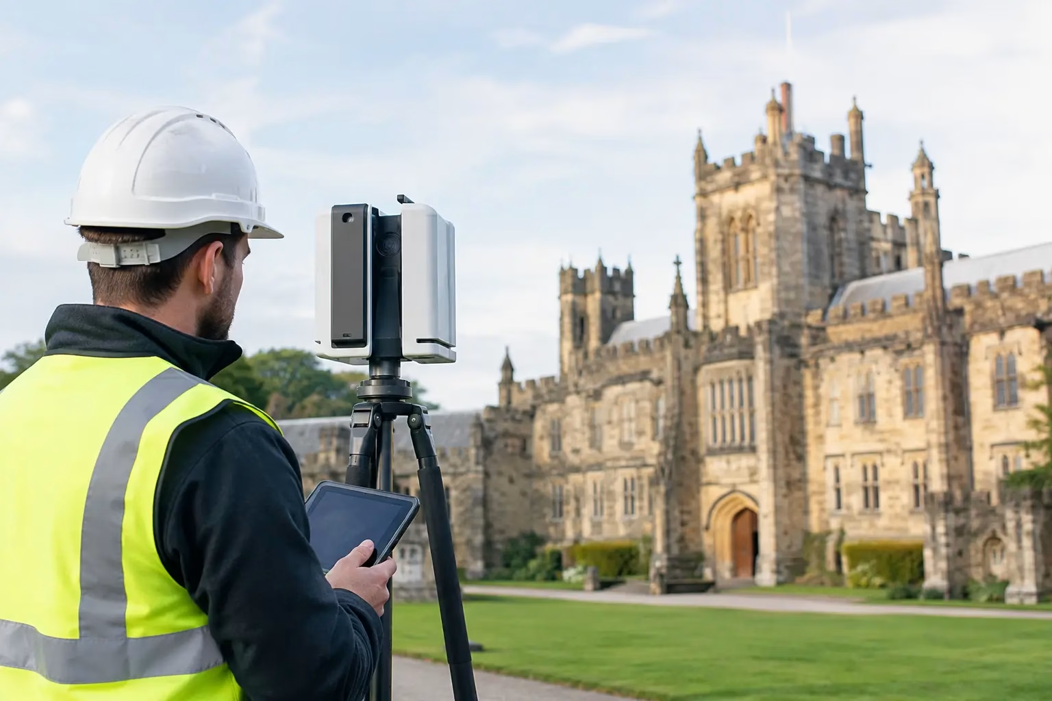
    A complex site rarely waits for a convenient survey window. Rail corridors, live industrial facilities, construction projects and heritage structures all demand reliable dimensions without unnecessary disruption or exposure to risk. 3D LiDAR scanning services provide a rapid way to capture dense, measurable spatial data and turn difficult environments into point clouds, drawings and models that project teams can use with confidence.

    For UK organisations, the value is not simply in collecting millions of points. It is in receiving the right level of accuracy, the right coordinate control and data outputs that fit design, inspection, construction or asset-management workflows.

    What 3D LiDAR scanning delivers

    LiDAR – Light Detection and Ranging – measures the distance between a sensor and surrounding surfaces using laser pulses. A terrestrial, mobile or drone-mounted scanner records these measurements at speed, building a detailed three-dimensional point cloud of the site.

    The point cloud is a spatial record rather than just a visual model. Individual points hold X, Y and Z positions and may also include colour imagery, intensity values or classification information. When survey control and processing are handled correctly, the data can be measured, sectioned, compared and converted into practical deliverables.

    Typical outputs include registered point clouds, 2D CAD plans, elevations and sections, mesh models, orthomosaics, digital terrain models, volumetric calculations and BIM-ready geometry. The appropriate output depends on the decision that needs to be made. A contractor setting out temporary works does not necessarily need the same model detail as a heritage consultant documenting an ornate façade.

    When a LiDAR survey is the right approach

    3D laser scanning is particularly effective where conventional measurement would be slow, unsafe or incomplete. It captures the wider context as well as the specific feature initially requested, allowing teams to revisit measurements in the point cloud without returning to site for every query.

    On construction and civil engineering schemes, scanning supports existing-condition surveys, progress capture, cut-and-fill calculations and design-versus-as-built comparisons. It can provide a dependable geometric baseline before work starts, then create an audit trail as the site changes.

    Infrastructure and utilities teams use LiDAR to record bridges, tunnels, substations, plant rooms, highways and drainage assets. The ability to collect information from a safe standoff position can reduce time spent in operational areas, at height or near live traffic. That said, scanning does not remove the need for a site-specific risk assessment, access planning and appropriate control measures.

    For forestry, land management and environmental work, airborne LiDAR can cover large areas efficiently and reveal terrain beneath partial canopy. Drone-based LiDAR is often suited to constrained sites or targeted corridors, while crewed airborne acquisition may be more economical for extensive estates. Ground cover, vegetation density, required point density and airspace constraints all affect the method selected.

    Heritage and property professionals benefit from detailed records of complex geometry, including listed façades, roofs, interiors and difficult-to-measure features. A high-resolution scan gives designers and conservation teams a measured reference that is far more complete than a limited set of manual dimensions.

    Choosing the right capture method

    The phrase LiDAR scanning can describe several acquisition methods. Selecting the correct one matters more than choosing the highest available specification.

    Terrestrial laser scanning

    Static terrestrial scanners are positioned at multiple stations around a site. They are well suited to buildings, structures, plant, interiors and detailed external surveys where high point density and precise geometric capture are required. Multiple scans are registered together, usually with survey control, to create a unified point cloud.

    This method is highly capable, but line of sight remains a practical limitation. Areas hidden behind machinery, stored materials or structural elements require additional scan positions or may remain inaccessible until conditions change.

    Mobile mapping and handheld LiDAR

    Mobile systems collect data while an operator walks, drives or moves through an environment. They can be exceptionally productive for large buildings, warehouses, corridors and external assets, particularly where rapid coverage is more valuable than the finest static-scan resolution.

    Their performance depends on the system, the route taken, GNSS availability where used, and the quality of simultaneous localisation and mapping processing. They are not a substitute for a control-led survey where tight tolerances are contractually required, but they can be the most efficient option for many reality-capture tasks.

    Drone LiDAR surveys

    Drone-mounted LiDAR combines laser scanning with aerial coverage. It is useful for stockpiles, quarries, inaccessible slopes, vegetation, linear infrastructure and sites where ground access is restricted. It can capture terrain and structures from above while keeping survey personnel away from hazardous ground.

    Weather, flight permissions, airspace, battery planning and vegetation conditions influence delivery. Photogrammetry may be a better fit where photographic texture is the main requirement and vegetation penetration is not needed. In many projects, LiDAR and photogrammetry work well together rather than competing.

    Accuracy is a workflow, not a headline figure

    Accuracy claims should always be considered in context. Scanner range accuracy is only one component of the final survey result. Control quality, instrument calibration, GNSS corrections, scan geometry, target placement, registration residuals and processing decisions all influence the accuracy of the delivered dataset.

    A project should begin with a defined specification: required coordinate reference system, vertical datum, target accuracy, feature scope, deliverable format and intended use. Without this, a technically impressive point cloud can still fail to meet the needs of a designer, quantity surveyor or asset manager.

    For example, a colourised point cloud may be ideal for visual coordination, but it is not automatically suitable for extracting precise steelwork dimensions. Similarly, a drone survey can map a site rapidly, yet canopy, shadowing and inaccessible control locations can affect confidence in particular areas. A professional service provider will identify these constraints before mobilisation rather than presenting a single capture method as the answer to every project.

    From point cloud to usable project data

    Raw capture is only the first stage. The commercial value of 3D LiDAR scanning services comes from turning that capture into information people can act on.

    Registration aligns individual scans or flight strips into a coherent dataset. Georeferencing places the data within the agreed national grid, local site grid or project coordinate system. Classification separates surfaces such as ground, buildings, vegetation and infrastructure, particularly in aerial datasets. Quality assurance checks coverage, alignment and control before downstream modelling begins.

    The required level of interpretation should be agreed early. A survey team may need a clean, registered point cloud for its own CAD technicians. Another client may require fully drawn floor plans, reflected ceiling plans, elevations and sections. For BIM applications, a model can be produced to an agreed level of definition, but this should not be confused with automatically converting every scan point into intelligent, verified building information.

    Clear scope prevents unnecessary cost and avoids mismatched expectations. It also allows the capture programme to focus on critical areas: connection points, service routes, structural interfaces, deformation zones or inaccessible assets.

    Planning a dependable LiDAR scanning project

    A successful survey is planned around the site and the decisions it must support. Before work begins, establish access arrangements, working hours, safety requirements, control information, security restrictions and any operational constraints. In live facilities, this may include inductions, escorts, shutdown windows or restrictions on photography and drone use.

    Provide existing drawings and coordinate information where available, but treat them as reference material until verified. Older drawings often contain discrepancies that are precisely why an as-built LiDAR survey is required.

    It is also worth deciding how data will be issued and managed. Large point clouds can be difficult to distribute through ordinary email systems and may require an agreed delivery platform, file structure and software compatibility check. CAD, BIM and GIS teams should be involved before capture, especially where a specific format or coordinate system is mandatory.

    LiDAR Tech UK supports organisations that need both capable capture technology and project delivery support. That joined-up approach is useful when an internal team wants to build its own scanning capability while retaining access to specialist guidance, processing expertise or additional survey resource for demanding projects.

    The result should be certainty, not just more data

    The best LiDAR survey is not defined by the size of its point cloud. It is defined by whether a design team can coordinate with fewer assumptions, whether an inspector can assess an asset without avoidable exposure, and whether a project can move forward with measured evidence rather than incomplete records.

    When capture method, control strategy and final deliverables are specified around the real task, 3D LiDAR becomes a practical route to faster decisions and more dependable project outcomes.

  • Drone Payload Selection Guide for Survey Teams

    Drone Payload Selection Guide for Survey Teams

    A professional drone is only as valuable as the data it produces. This drone payload selection guide is designed for survey, engineering and inspection teams that need to match the right sensor to a defined output, accuracy requirement and site workflow. Choosing by headline specification alone can lead to incomplete datasets, inefficient flights or a payload that cannot support the intended deliverable.

    The correct decision begins before aircraft selection. Establish what the client, design team or asset owner needs to receive: a georeferenced orthomosaic, CAD-ready topographic survey, classified point cloud, thermal report, high-resolution inspection imagery or a repeatable progress record. The payload should then be selected around that outcome, not around the broadest list of advertised capabilities.

    Start with the required deliverable

    Payload choice changes materially between mapping, inspection and measurement applications. A camera that produces excellent visual documentation may not be suitable for dense vegetation modelling. Equally, a LiDAR sensor capable of recording ground returns beneath canopy may be unnecessary for a straightforward stockpile calculation on an open site.

    For construction and earthworks, the usual objective is an accurate terrain model, volume calculation or progress dataset. Photogrammetry can be highly effective on open, textured ground where sufficient image overlap, ground control or RTK positioning and suitable lighting are available. LiDAR becomes more compelling where surfaces are complex, time on site is limited, or vegetation and variable light make image-based processing less dependable.

    For infrastructure inspections, the output often requires detail rather than broad-area coverage. A high-resolution visual camera with strong zoom capability can reduce the need for personnel to access roofs, façades, bridges, telecoms structures or hazardous industrial assets. Thermal imaging should be selected only where temperature variation is relevant to the inspection decision, such as identifying heat loss, overheating electrical components, moisture-related anomalies or solar panel defects.

    This distinction matters commercially. A more expensive payload does not automatically produce a more useful survey. The value lies in producing defensible, analysis-ready data with the fewest site visits, safest field method and most efficient processing route.

    Match the sensor to the site conditions

    The operating environment is frequently the factor that determines whether photogrammetry, LiDAR, thermal or visual zoom is the appropriate approach. Consider the physical site before comparing sensor specifications.

    Photogrammetry payloads for open and visible surfaces

    A calibrated RGB camera is often the practical choice for earthworks, quarries, construction progress, façade capture and open-site mapping. It can produce detailed orthomosaics, textured meshes and point clouds when the ground is visible and flight planning is controlled.

    Image quality depends on light, texture, shutter settings, motion blur and overlap. Smooth, reflective or repetitive surfaces can create reconstruction issues. Shadows can also reduce consistency between images, particularly on deep excavations, urban streets and sites with tall structures. A large sensor and mechanical shutter may improve results, but field planning still determines whether the imagery is survey-grade.

    Where absolute accuracy is required, assess the complete georeferencing method. RTK-equipped aircraft can reduce dependence on ground control points, but independent check points remain good practice for validating results. Project tolerances, survey control, GNSS visibility and client specification should determine the control strategy.

    LiDAR payloads for terrain, vegetation and complex geometry

    Airborne LiDAR records direct range measurements, making it well suited to topographic mapping, corridor surveys, forestry, utility routes and complex built environments. Its key advantage is the ability to capture a dense three-dimensional point cloud without relying on surface texture or consistent daylight.

    For vegetation-covered sites, a multi-return LiDAR system can record returns from canopy, understory and ground. This gives survey teams a clearer route to deriving a bare-earth terrain model, although point density, flight height, scan pattern and canopy density will affect the final ground coverage. LiDAR is not a guarantee of a perfect ground model through every woodland type, but it can substantially reduce the limitations of image-based methods.

    Accuracy is determined by more than the sensor’s stated ranging precision. GNSS and IMU performance, trajectory processing, boresight calibration, flight speed, overlap, base station or network corrections, and quality assurance all contribute to the result. A payload should therefore be assessed as part of an integrated survey system rather than as an isolated sensor.

    Thermal payloads for condition-led inspections

    Thermal cameras measure apparent surface temperature, not a direct diagnosis of fault or failure. They are useful where a temperature anomaly supports an inspection decision, but results must be interpreted with an understanding of emissivity, reflected temperature, weather conditions, viewing angle and operating load.

    For example, an electrical inspection requires appropriate load conditions to reveal meaningful variation. A roof survey may need stable weather and consideration of solar gain. Resolution also matters: a wide-area thermal survey may identify an area of concern, while close-range work may be needed to verify a small component anomaly. Pairing thermal data with a visual camera is usually the most effective approach because it provides both evidence of the anomaly and clear asset context.

    Zoom cameras for safe visual inspection

    Optical zoom payloads are designed for close visual assessment from a controlled standoff distance. They are particularly useful for high-level or inaccessible assets where an inspector needs to read labels, inspect joints, identify surface deterioration or document a defect without working at height.

    The relevant specification is not zoom alone. Evaluate effective image resolution at the required distance, stabilisation, autofocus behaviour, low-light performance and the aircraft’s ability to hold position safely. At long focal lengths, small aircraft movements become more visible, so wind conditions and pilot technique have a direct impact on usable imagery.

    Check aircraft and payload compatibility

    A payload may suit the application but still be unsuitable for the aircraft, crew or site. Enterprise drone selection should consider payload weight, power draw, flight time, operating temperature, wind tolerance, ingress protection and transport requirements. A heavier sensor may provide more data per flight but reduce endurance and increase the number of battery changes needed across a large site.

    Integration also affects operational confidence. Native payloads designed for a specific enterprise airframe generally provide predictable control, live view, metadata recording and mission-planning support. Third-party integrations may offer specialist capability, but teams should confirm mounting, power, data storage, time synchronisation and support arrangements before committing to a workflow.

    For UK operations, site permissions and airspace constraints can be as significant as sensor choice. Restricted areas, proximity to people, nearby infrastructure, take-off and landing space, and weather windows may limit the aircraft size or flight profile available. A technically capable payload is of little value if the practical operating method cannot be deployed safely and compliantly.

    Plan for positioning, control and data processing

    Payload selection should include the entire data chain. For survey-grade work, this means considering RTK or PPK capability, correction source, base station arrangements, coordinate reference systems and the method used to verify accuracy. Positioning errors can undermine excellent sensor data, particularly where the final output must align with existing design models, utility records or previous surveys.

    Processing capacity is equally important. LiDAR workflows require point cloud registration, trajectory refinement, classification and export to the formats used by CAD, GIS or modelling teams. Photogrammetry requires image alignment, dense reconstruction, quality checks and suitable control. Thermal inspections need radiometric data handling if temperatures must be analysed rather than simply viewed as colour imagery.

    Ask practical questions before purchase: who will process the data, how quickly is a deliverable needed, what software is already used, and what level of quality assurance will be documented? The most suitable payload is one that fits the organisation’s field skills and office workflow without creating a costly processing bottleneck.

    Compare capability against total project cost

    Purchase price is only one part of payload value. Consider training, batteries, RTK corrections, survey control, software licences, processing time, maintenance, insurance and the cost of repeat visits. A lower-cost visual payload may be the right commercial choice for routine documentation, while a LiDAR system can be justified where it replaces extensive ground survey, reduces exposure to difficult terrain or supports repeatable asset datasets.

    Hiring or outsourcing can also be appropriate for occasional specialist work. It allows teams to test whether a LiDAR or thermal workflow produces enough operational value before investing in equipment and internal capability. For organisations building a regular drone programme, practical training and technical support are often as important as the selected airframe and sensor.

    LiDAR Tech UK can help assess payload options against project tolerances, site conditions and the required data format, whether the need is equipment supply, workflow implementation or delivered survey data.

    The best payload decision is usually the one that makes the final deliverable routine rather than exceptional. Define the result, validate the accuracy route and test the workflow on representative sites before standardising a fleet.

  • Drone Surveying for Civil Engineering Projects

    Drone Surveying for Civil Engineering Projects

    A missed stockpile volume, an out-of-date topographic survey or an inaccessible structure can quickly affect a civil engineering programme. Drone surveying for civil engineering gives project teams a faster way to capture current, measurable site information without putting surveyors in avoidable risk or disrupting active works.

    For UK contractors, consultants and infrastructure owners, the value is not simply aerial imagery. A properly planned drone survey can produce georeferenced orthomosaics, point clouds, digital terrain models, contours, cut-and-fill calculations and 3D models that support decisions from feasibility through to handover. The outcome depends on selecting the right sensor, control method and processing workflow for the required accuracy.

    Where drone surveying delivers value on civil sites

    Civil projects change rapidly. Earthworks move, access routes shift, temporary works appear and progress against programme needs to be verified. Traditional field survey remains essential, particularly where precise set-out and detailed verification are required, but drones can capture broad areas far more efficiently than conventional methods alone.

    Aerial photogrammetry is particularly effective for open sites with visible ground surfaces. Images captured in a structured flight pattern are processed into a dense point cloud and mapped products. For a road corridor, housing development, quarry or flood-alleviation scheme, this can provide a current overview of the entire working area in a single survey visit.

    Common applications include topographic mapping, earthworks quantity measurement, construction progress records, drainage and highway inspections, haul-road monitoring, vegetation assessment and site logistics planning. Repeatable flight plans also make it easier to compare the same area over time, allowing teams to identify change rather than relying solely on isolated site photographs.

    The commercial benefit is clear when data reaches the design, commercial and construction teams promptly. A survey that once required multiple days of ground observation may be captured in a few hours, subject to site size, airspace, weather and control requirements. Processing and quality assurance still take time, but the field operation is often substantially shorter.

    Accuracy is a workflow, not a drone specification

    A drone fitted with RTK positioning can improve geotagging accuracy and reduce the amount of ground control needed. It does not remove the need to validate results. The final accuracy of a survey depends on several connected factors: GNSS correction quality, camera calibration, flight height, image overlap, ground conditions, control distribution, processing settings and independent checkpoints.

    For many earthworks, planning and progress applications, RTK drone photogrammetry with well-distributed checkpoints can provide highly useful centimetre-level site data. Where contractual tolerances are tighter, or where outputs will inform design and setting-out decisions, a more rigorous control network and verification approach is required.

    Ground control points establish a known reference across the survey area. Checkpoints are surveyed independently and used to test the output rather than influence it. This distinction matters. A model can appear accurate when assessed only against the control used to create it, while independent checkpoints reveal whether that accuracy is consistent across the site.

    Coordinate reference systems also need attention. UK projects commonly require data in British National Grid and Ordnance Datum Newlyn, but client specifications, local grids and BIM workflows may vary. Establishing the required datum and deliverable format before flying prevents expensive reprocessing and avoids data being overlaid incorrectly in CAD or GIS.

    When photogrammetry is not enough

    Photogrammetry requires clear visual texture and line of sight to the surface. It performs well over exposed aggregate, compacted fill, road surfaces and buildings, but it may struggle with dense vegetation, deep shadow, reflective water or featureless surfaces.

    LiDAR can be a better choice where vegetation obscures the ground, where vertical features need detailed capture, or where a high-density 3D point cloud is required. A drone LiDAR survey can record multiple returns through gaps in foliage, supporting terrain modelling in woodland, embankment assessment and utility corridor surveys. It is not automatically the preferred option, however. LiDAR systems typically involve a higher equipment and processing cost, and the required point density, accuracy and site conditions should justify that investment.

    In practice, many schemes benefit from both methods. LiDAR provides dependable surface geometry and terrain penetration, while high-resolution imagery adds visual context for design review, reporting and asset identification.

    A practical survey workflow for engineering teams

    The best drone surveys begin before the aircraft is on site. The survey brief should define the area, intended decisions, required accuracy, coordinate system, delivery deadline and final outputs. “Aerial images of the site” is not an adequate scope if the commercial team needs defensible volume calculations or designers need CAD-ready terrain data.

    A competent workflow usually includes the following stages:

    • A desk study covering site boundaries, airspace restrictions, nearby infrastructure, take-off and landing areas, hazards and permissions.
    • A site control plan using GNSS equipment, existing verified control or a combination of RTK corrections and checkpoints.
    • A flight plan matched to the terrain, sensor, ground sampling distance and required overlap.
    • Field capture with documented weather, visibility, control observations and any areas that could not be surveyed safely.
    • Processing, classification, quality assurance and delivery in agreed formats such as LAS, LAZ, DWG, DXF, GeoTIFF, PDF or machine-control-compatible surfaces.

    This process should remain proportionate. A small stockpile survey does not need the same control density as a linear infrastructure scheme extending several kilometres, yet both require a clear method and evidence that the results are fit for purpose.

    Better earthworks measurement and progress control

    Earthworks are one of the strongest use cases for drone data because changes are both frequent and expensive. A current terrain model can be compared against design surfaces to calculate cut and fill, identify over-excavation or assess whether material movements align with the programme.

    Volume outputs are only as reliable as the surveyed surface and the agreed measurement rules. Teams should establish the base surface, stockpile boundaries, void handling and reporting units in advance. For example, a stockpile volume measured against an assumed flat base may differ materially from one calculated against a surveyed pre-existing surface.

    For progress reporting, orthomosaics and 3D models provide a visual record that is easier for non-survey stakeholders to interpret. They can show completed drainage runs, pavement layers, compound changes and access constraints across the full site. Used alongside site diaries and programme information, the data offers a defensible record of what was visible on a particular date.

    Safety, compliance and operational constraints

    A drone survey should reduce exposure to risk, not introduce another unmanaged activity. Keeping surveyors away from steep slopes, unstable stockpiles, live carriageways, rail environments and hazardous structures is a major advantage. It does not eliminate the need for a site-specific risk assessment, method statement and coordination with the principal contractor.

    UK operations must comply with Civil Aviation Authority requirements. The applicable operational category, pilot competency, operator registration, aircraft weight, proximity to people and airspace all affect what can be flown and how. Some sites require additional coordination because of controlled airspace, heliports, prisons, critical national infrastructure, rail corridors or public access.

    Weather is a practical constraint as well as a safety consideration. Strong wind, rain, low cloud and poor light may affect both flight safety and image quality. Good survey planning includes contingency time rather than treating a drone flight as guaranteed simply because the equipment is available.

    Choosing between in-house capability and a survey service

    Owning an enterprise drone can be commercially sensible for organisations with regular, repeatable survey or inspection needs. It gives site teams more control over capture timing and allows frequent progress records without arranging an external visit for every flight.

    However, the purchase price is only one part of the decision. Training, CAA compliance, insurance, RTK corrections, software licences, batteries, maintenance, processing capability and quality assurance all need to be considered. An in-house team also needs a defined route from raw imagery to checked engineering deliverables.

    Outsourcing can be the stronger option for one-off schemes, technically demanding sites or projects requiring specialist LiDAR capture and independently verified survey outputs. A hybrid model is often effective: site teams capture routine progress imagery, while a specialist provider completes baseline topographic surveys, periodic volume checks or complex inspection work.

    LiDAR Tech UK supports this decision from both sides, supplying professional drone, GNSS and LiDAR systems while providing training, technical support and survey services where project delivery is required.

    Specify the output before you specify the aircraft

    The question is rarely “Which drone should we buy?” It is “What decision must this data support, and what evidence will demonstrate that it is accurate enough?” A visual progress record, a design-grade terrain model and a vegetated corridor survey may all involve a drone, but they demand different equipment, controls and checks.

    Define the required deliverable, accuracy and programme first. The right drone survey workflow can then turn a changing site into reliable, usable engineering data rather than another folder of aerial photographs.

  • What Equipment Is Needed for RTK Surveying?

    What Equipment Is Needed for RTK Surveying?

    Centimetre-level positioning is only useful when every part of the workflow is working together. For organisations asking what equipment is needed for RTK surveying, the short answer is a capable GNSS receiver, a correction source and a practical way to collect, check and export field data. The right specification depends on whether the job is setting out, topographic survey, machine control, utility work or rapid site capture.

    RTK, or Real-Time Kinematic positioning, uses carrier-phase GNSS measurements and live corrections to reduce the errors that affect standalone satellite positioning. When the solution is fixed and site conditions are suitable, an RTK system can deliver repeatable centimetre-level results in real time. That performance is not automatic: sky visibility, mobile signal, correction quality, datum control and operator procedure all matter.

    The core equipment needed for RTK surveying

    A professional RTK survey setup has four functional elements: a rover that measures position, a correction source that supplies reference data, a controller or application that manages the survey, and field accessories that keep the system stable and operational. In many cases, the rover and controller form a compact, connected package. The correction source may be a local base station or a network RTK service.

    1. A multi-constellation GNSS RTK rover

    The rover is the primary field instrument. Mounted on a survey pole, it receives signals from satellite constellations such as GPS, Galileo, GLONASS and BeiDou, then applies real-time corrections to calculate its position. For professional work, choose a receiver designed for multi-constellation and multi-frequency operation. More tracked signals improve the opportunity to maintain a fixed solution where visibility is restricted by buildings, trees or plant.

    Receiver specification should be judged against the environments your teams actually work in. Key considerations include stated RTK horizontal and vertical accuracy, time to fix, tilt compensation, ingress protection, operating temperature, battery endurance and the quality of the internal radio and cellular modem. A receiver with IMU-based tilt compensation can speed up collection around walls, fences and obstructions because the pole does not need to be held perfectly plumb. It does not remove the need for sound checking procedures, particularly on control or setting-out work.

    For UK survey workflows, it is also sensible to confirm support for the coordinate reference systems, transformations and grid settings required by your client or project. A precise receiver using the wrong coordinate system will still produce the wrong answer.

    2. A correction source: network RTK or a base station

    An RTK rover needs correction data from a reference receiver with a known position. The most common option is a network RTK correction service delivered over the mobile internet. The rover connects through a SIM card or paired controller, receives corrections via NTRIP and applies them while observations are taken. This is usually the most efficient choice for teams working across multiple sites, provided dependable mobile coverage is available.

    A local base station is the alternative. It is another GNSS receiver placed over a known control point, or over a point established through an appropriate localisation procedure. The base transmits corrections to the rover by UHF radio or, in some configurations, through the internet. A base-and-rover kit is valuable on remote sites with weak mobile coverage, for isolated work areas, or when a contractor needs direct control of the correction source.

    The trade-off is operational responsibility. A base must be set up correctly, protected from disturbance, powered throughout the survey and referenced properly. If its assumed coordinates are incorrect, every rover point will inherit that error. Network corrections reduce the field setup burden but introduce reliance on a subscription, mobile data and the network’s availability.

    3. A field controller and survey software

    The controller is where field measurements become usable survey information. This may be a rugged handheld data collector, a tablet or, for lighter duties, a mobile device running compatible software. Professional survey applications allow the operator to select coordinate systems, connect to corrections, monitor solution status, code features, stake out coordinates, navigate to lines and surfaces, and export results in the required format.

    For topographic work, feature coding and linework collection can substantially reduce office processing. For setting out, the controller should support CAD or design data, clear cut-and-fill guidance and tolerances suited to the construction task. For asset capture, configurable forms can standardise attributes such as asset type, condition, material, photographs and inspection notes.

    Do not select a controller purely on screen size. It needs a daylight-readable display, a responsive touch interface that works with gloves where required, sufficient battery capacity, stable connectivity and an operating system supported by the GNSS manufacturer’s software. The field workflow should also integrate cleanly with the office software used for CAD, GIS, design models or reporting.

    4. Survey pole, mounting hardware and accessories

    The pole may look secondary, but it is part of the measurement system. Use a rigid, calibrated carbon-fibre or aluminium survey pole with a clear height mark and a suitable bipod for static observations or repeatable control checks. The antenna height entered in the software must match the actual setup. A loose clamp, damaged pole tip or unverified pole length can undermine otherwise excellent GNSS results.

    A practical field kit should include:

    • spare batteries and charging equipment sized for a full shift;
    • a protective case, cleaning materials and weather-appropriate covers;
    • a SIM card and data plan when using network corrections;
    • a radio antenna and cables when operating a local UHF base; and
    • a tape measure, marker materials and basic control-point documentation.

    For long days, high-output charging in the vehicle can prevent downtime. Battery planning is especially relevant in cold weather, where capacity can fall and tablet screens can become less responsive.

    Choosing between a rover-only and base-and-rover RTK system

    A rover-only system connected to a correction network is often the best commercial starting point. It is quick to deploy, reduces equipment carried to site and supports flexible working across a broad area. It suits routine topographic surveys, site verification, volume checks, utility mapping and many construction tasks.

    A base-and-rover system gives greater independence and can be the better option for remote infrastructure, forestry, large rural estates and locations where mobile data is unreliable. It is also useful where a project has an established control network and the survey team needs a dedicated local reference. However, it requires more training, more setup time and disciplined control management.

    Some organisations need both. A rover can use network corrections on accessible sites and switch to a local base where coverage or project requirements demand it. This approach is often more resilient than treating one correction method as suitable for every job.

    Accuracy depends on more than the hardware

    Published RTK accuracy figures are achieved under stated conditions, usually with a fixed solution, good satellite geometry and suitable correction data. A receiver may display a highly precise position while still being affected by multipath, where signals reflect from buildings, vehicles, metal fencing or water. Dense canopy and narrow urban corridors can also interrupt satellite tracking.

    Operators should confirm that the receiver has achieved a fixed RTK solution before accepting critical points. Check measured control points at the beginning and end of the session, observe important positions more than once and investigate any discrepancy rather than averaging it away. For work tied to legal boundaries, engineering tolerances or third-party design control, establish the required verification procedure before mobilisation.

    Vertical results deserve particular attention. GNSS measures height relative to an ellipsoid, while UK projects may require orthometric levels related to a recognised vertical datum. The correct geoid model, transformation and project settings must be applied consistently from field collection to final deliverables.

    Equipment decisions by application

    For construction setting out, prioritise fast fixed solutions, tilt compensation, reliable CAD stake-out tools and clear control verification. A rugged controller and strong support for design-file import will often have more value than adding unnecessary survey modes.

    For land and topographic survey, feature coding, linework collection, repeatable pole setup and direct export to CAD or GIS are central. A rover with network RTK can provide an efficient daily workflow where mobile coverage is sound.

    For forestry, utilities and asset inspections, select a receiver that performs well under partial canopy and pair it with data-collection forms that capture attributes consistently. GNSS may need to be supplemented by total station, mobile mapping or LiDAR where satellite visibility is poor or detailed geometry is required.

    For drone ground control, the requirement is not simply an RTK rover. The team also needs a defined control strategy, stable targets where appropriate, coordinate-system discipline and independent check points. An RTK drone can reduce the amount of ground control required, but it does not remove the need to validate the final mapping output.

    Build the workflow, not just the kit list

    The best RTK purchase is one that supports the full route from control to deliverable. That means confirming correction coverage, coordinate reference requirements, controller software, export formats, staff training and a support route before equipment reaches site. LiDAR Tech UK can help organisations match GNSS hardware, correction workflows and survey software to the accuracy, environment and output requirements of their projects.

    Before committing to a system, test it against a representative site and a real deliverable. A short field demonstration that proves fix reliability, coding speed and office compatibility will tell you far more than a specification sheet alone.

  • Guide to NTRIP Corrections for Survey Teams

    Guide to NTRIP Corrections for Survey Teams

    A rover can report a fixed RTK solution and still produce poor survey data if its correction workflow is not properly specified, configured or monitored. This guide to NTRIP corrections for survey teams explains how internet-delivered GNSS corrections work in the field, where accuracy can be lost, and how to build a workflow that stands up to professional survey control.

    NTRIP is now a practical alternative to deploying a local base station for many UK surveying, construction and asset-capture jobs. It can reduce equipment on site and speed up mobilisation. However, it relies on more than a mobile-data signal and a valid subscription. The coordinate reference frame, correction source, mountpoint, latency and field verification process all affect the result.

    What NTRIP corrections do

    NTRIP stands for Networked Transport of RTCM via Internet Protocol. In practical terms, it is the method used to stream GNSS correction data from a reference-station network to an RTK rover over the internet.

    A GNSS receiver calculates its position from satellite signals. Those signals are affected by orbit and clock errors, atmospheric delay, multipath and other sources of uncertainty. An NTRIP correction service uses known reference-station positions to model or measure these errors and send correction messages to the rover. With compatible multi-constellation, multi-frequency hardware, the rover can resolve carrier-phase ambiguities and achieve centimetre-level positioning when conditions are suitable.

    The phrase “when conditions are suitable” matters. RTK is not a guarantee of a particular accuracy at every point on every site. Dense tree canopy, nearby steelwork, reflective façades, restricted sky view and poor mobile coverage can all reduce performance. Corrections improve the satellite solution; they do not remove the need for sound survey practice.

    Choose the right correction source

    Survey teams generally use either a single-base stream or a network RTK service. A single-base stream sends corrections from one known reference station. It can be effective where the baseline is short and the base position, datum and antenna setup are controlled. It is common on projects that establish their own base for a defined site and timescale.

    A network RTK service uses multiple permanent reference stations. The network models spatially varying errors and provides a correction stream designed for the rover’s approximate location. For teams working across multiple sites, it is usually the more efficient option because there is no daily base-station deployment or requirement to secure a base over a known point.

    The right choice depends on the work. A local base can give a controlled project setup in areas with unreliable mobile coverage, provided its coordinates are correctly established. Network RTK is often better for rapid topographic work, setting out, utility mapping, drone ground control and mobile LiDAR workflows where travel and setup time are significant.

    Do not select a service solely because it returns a fixed solution quickly. Confirm the coordinate reference system and transformation offered by the service, the expected coverage in your operating area, supported RTCM message types, user limits and technical support arrangements. A correction source that is accurate in the wrong datum is still wrong for the project.

    Configure the rover correctly

    Most current professional GNSS rovers can connect directly to NTRIP using an internal SIM, an external controller with mobile data, or a phone hotspot. Direct SIM connectivity is often the cleanest field setup, while a controller connection can be useful where the survey software manages network settings and job profiles in one place.

    Create a dedicated profile for each correction service. Enter the caster address, port, username, password and mountpoint exactly as supplied. The mountpoint is not simply a label: it determines the correction stream the rover receives. Selecting a nearby-looking mountpoint without understanding its format can lead to an unsuitable stream or a position outside the required coordinate framework.

    Before leaving the office, verify that the receiver firmware and field software support the selected correction format, typically RTCM 3.x. Set the correct antenna model and measured pole height. For a tilt-compensated rover, follow the manufacturer’s calibration procedure and check that tilt compensation is enabled only when the hardware is intended to use it.

    The project coordinate system deserves the same attention. Your site grid may be based on British National Grid, a local engineering grid, a client-defined coordinate system or a transformation from ETRS89-based GNSS coordinates. Configure the transformation and geoid model required for the deliverable, particularly if you are producing levels, setting out design data or combining observations with total-station control.

    Why heights cause avoidable errors

    GNSS naturally derives an ellipsoidal height, while construction and survey deliverables frequently require an orthometric height related to a geoid model or local benchmark system. If the wrong geoid is selected, horizontal coordinates may look credible while levels are consistently wrong.

    This is why a control-point check must assess both plan and height. Never assume that a fixed RTK status means the height is suitable for formation levels, drainage work or detailed design verification.

    A field workflow that protects accuracy

    A reliable NTRIP workflow begins with a known point. Occupy a project control mark before production work and compare the measured coordinate with the approved value. Record the difference in easting, northing and height, together with the correction service, mountpoint, time, solution status and pole-height settings.

    If the result is outside project tolerance, stop and investigate. Common causes include an incorrect coordinate system, wrong geoid, incorrect antenna height, a changed mountpoint, loss of fixed status or a poorly defined control coordinate. Repeating an observation without identifying the source of error can simply repeat the same error.

    During work, watch solution status, correction age, estimated precision and satellite availability. A fixed solution with low correction age is normally the expected production condition. A float solution may be useful for navigation or locating an approximate feature, but it should not be accepted for survey-grade observations unless the project specification expressly allows it.

    A practical daily routine should include:

    • checking into at least one approved control point at the start of the shift;
    • confirming fixed status, correction age and the correct project coordinate system before capture;
    • rechecking control after a significant outage, receiver restart or move between work areas;
    • recording independent check shots at suitable intervals; and
    • retaining raw observations, field logs and quality records with the project data.

    The frequency of independent checks should reflect the risk. A simple boundary survey on open ground has different consequences from setting out bridge bearings, recording buried utility positions or establishing drone ground control for a high-value corridor project.

    Mobile data, latency and coverage

    NTRIP depends on a data connection, but it does not consume large volumes of data. The greater risk is interruption or delay. In urban locations, network coverage can vary sharply between streets, inside cuttings, beside structures and on lower ground. Rural projects may need a coverage review before mobilisation.

    Correction age is a useful live indicator. If the correction age is increasing, the rover may still show a fixed solution for a short period, but the link is no longer healthy. Pause observations when corrections are stale. Reconnect, confirm the stream has resumed and reoccupy a known point before restarting production.

    For critical work, build resilience into the method statement. This may mean carrying a local base station, using a controller and rover with separate network options, retaining an alternative SIM, or scheduling satellite visibility around obstructed areas. There is no universal backup arrangement: it depends on site remoteness, tolerances, programme pressure and the cost of a return visit.

    Common NTRIP problems and what they indicate

    A rover that will not fix may have poor sky view, an unsuitable mountpoint, an incompatible correction format, a long baseline, outdated firmware or a weak mobile-data connection. Start with the simple checks: confirm internet access, credentials, correction age, constellation tracking and antenna setup. Then test in an open-sky area before assuming the issue is with the correction provider.

    A consistent coordinate offset normally points to a datum, transformation, geoid or local-grid issue rather than random GNSS error. A variable offset that changes by position or time is more likely to involve multipath, canopy, obstruction, correction interruption or unstable field practice.

    Where results must tie precisely to existing control, use a check point and document the comparison. This protects the project and provides the evidence needed to resolve any dispute between design coordinates, legacy control and GNSS-derived positions.

    Guide to NTRIP corrections for survey teams: buying decisions

    When specifying an NTRIP-enabled GNSS solution, consider the complete workflow rather than the rover specification alone. The receiver should support the constellations and frequencies needed for your environment, but the survey software, correction service, coordinate-system tools, SIM arrangement, training and technical support are equally relevant.

    For organisations running multiple crews, standardised profiles and a documented control-check procedure usually deliver more value than marginal differences in headline accuracy. They reduce setup variation between operators and make survey data easier to audit.

    LiDAR Tech UK can help teams assess RTK rover capability, correction connectivity and the wider capture workflow around mapping, construction and spatial-data delivery. The aim is not simply to obtain a fixed solution, but to establish repeatable field results that align with the project specification.

    Before the next mobilisation, test the complete setup on known control in the same coordinate system you will use on site. A ten-minute check in the yard can prevent a day of rework in the field.

  • Survey Equipment Training for Accurate Fieldwork

    Survey Equipment Training for Accurate Fieldwork

    A GNSS rover, mobile LiDAR scanner or enterprise drone only delivers its specified performance when the operator understands the complete workflow around it. Effective survey equipment training turns a hardware purchase into dependable site data: correctly referenced, checked in the field and ready for CAD, GIS, modelling or asset-management use.

    For survey practices, contractors and asset owners, the commercial case is straightforward. A missed coordinate system setting, poor control arrangement or incomplete scan can create costly revisits, delay design decisions and undermine confidence in the final deliverable. Training reduces those risks while helping teams work faster and more safely.

    What professional survey equipment training should achieve

    Training should not stop at showing an operator which buttons to press. A productive programme gives the team enough practical understanding to plan a capture, configure equipment, recognise poor-quality observations and produce a usable output.

    The required depth depends on the role. A site engineer using an RTK rover for setting out needs a different level of knowledge from a surveyor establishing control for a corridor survey. Likewise, a drone pilot responsible for data capture must understand mission planning and image overlap, while the person processing the dataset needs to recognise whether the outputs meet the project specification.

    The best training is therefore built around actual applications rather than generic demonstrations. These may include topographic surveys, stockpile volumes, highway assets, façade capture, drainage works, forestry mapping or progress monitoring. The equipment settings, control strategy and quality checks should reflect the job the team is expected to complete.

    Start with control, coordinates and accuracy

    The most sophisticated scanner cannot correct a weak control framework. Before focusing on speed or point-cloud density, operators should understand how project coordinates are defined and how measurements relate to the required datum, grid and height system.

    For GNSS and RTK work, this includes selecting the correct coordinate reference system, connecting reliably to an appropriate correction source and confirming the rover has achieved a fixed solution. Operators should know the difference between a float and fixed position, how antenna height is entered, and when satellite geometry, multipath or obstruction make a reading unsuitable.

    Height is a common source of avoidable errors. Ellipsoidal height, orthometric height and site datum are not interchangeable. A team may collect positions that appear consistent in the field but are offset when combined with design data or legacy surveys. Training should make the required vertical reference explicit before the first point is measured.

    A sound field routine includes independent checks. Establish or occupy known points, record the result, and investigate discrepancies before progressing. On a high-value job, checking the same point from a separate occupation or using an alternative method provides greater assurance than relying on a single acceptable reading.

    Training for GNSS rovers and total field workflows

    GNSS equipment is fast and highly effective in open conditions, but it is not the right method for every feature. Buildings, dense canopy, retaining walls, bridges and plant can block or reflect satellite signals. Survey equipment training should help operators decide when to use RTK, when to supplement it with another method and when a different capture approach is more efficient.

    A practical GNSS session should cover configuration, pole setup, tilt compensation where fitted, coding, stake-out and as-built checks. It should also address feature attribution. A coordinate without a clear code, description or photograph may have limited value once it reaches the office.

    For construction applications, training should include loading the approved design surface or alignment, checking units and tolerances, and clearly separating design data from measured data. Operators need to understand that a successful stake-out result depends on both the quality of the control and the validity of the design file.

    Mobile LiDAR training: capture is only half the job

    Mobile LiDAR can collect millions of points quickly, making it valuable for complex buildings, highways, industrial sites and inaccessible assets. Its speed can also conceal problems until processing begins. A useful course teaches the relationship between scanning path, overlap, feature geometry and final point-cloud quality.

    Operators should be trained to plan routes that provide sufficient coverage and loop closures, particularly in long corridors or areas with repetitive surfaces. They must also consider walking speed, scanner settings, lighting where imagery is used, and the likelihood of moving vehicles or people introducing unwanted data.

    Control and verification remain essential. Depending on the system and required specification, this may involve surveyed targets, check points, known features or comparison against independent observations. A scan that looks visually convincing is not automatically survey-grade. The point cloud should be assessed for alignment, completeness, noise and agreement with control before it is issued or used for measurement.

    Processing instruction matters just as much as field operation. Teams should understand how to transfer and organise raw files, apply trajectories and control, register datasets, classify points and export the required format. The right deliverable may be a registered point cloud, mesh, orthophoto, measured drawing, digital terrain model or CAD-ready data. It depends on the client’s decision-making need, not simply on what the software can produce.

    Enterprise drone training requires operational discipline

    Drone surveys can reduce time spent working near traffic, unstable ground, roofs, structures and difficult terrain. They also introduce responsibilities that are not solved by flight skill alone. Training should cover pre-flight planning, airspace and site constraints, weather assessment, battery management, emergency procedures, payload setup and safe launch and recovery areas.

    For photogrammetry, image quality and overlap directly affect the model. Flight height, ground sampling distance, shutter settings, camera angle and route design need to be selected against the required accuracy and level of detail. A stockpile survey and a detailed façade inspection demand different flight patterns.

    Where survey accuracy is required, operators need a clear control strategy. RTK-enabled drones can improve positional efficiency, but project control and independent checkpoints may still be necessary for verification. This is particularly relevant where results will inform quantities, design changes, legal boundaries or asset condition decisions.

    Training should also establish a defensible record-keeping process. Flight logs, control observations, weather notes, approvals and data checks form part of a professional survey record. They are useful when clients ask how an output was produced or when a dataset needs to be revisited months later.

    Build quality assurance into the field routine

    The most valuable training outcome is a team that can identify a problem before leaving site. Field QA is normally faster and less expensive than discovering an issue during processing or after data has been delivered.

    A good routine covers equipment calibration and firmware status, battery capacity, storage availability, coordinate settings, control checks and coverage checks. For LiDAR, this may mean reviewing scan completeness and confirming the route has closed as planned. For drone work, it includes checking image exposure, overlap and any gaps in coverage. For GNSS, it means reviewing solution status, precision indicators and redundant observations.

    Teams should be encouraged to record exceptions rather than work around them silently. If access was restricted, a feature was obscured or a control point was disturbed, that information is material to the final survey. Clear site notes allow the office team to make informed processing decisions and give the client an honest view of any limitations.

    Choose training that matches the workflow

    Off-the-shelf equipment familiarisation has value, particularly for new users. However, organisations often gain more from training configured around their equipment, software, correction service and normal project types. This shortens the route from first use to billable work.

    When assessing a provider, look for practical field experience as well as product knowledge. The training should cover setup and operation, but also data handling, troubleshooting, accuracy validation and the handover between field and office. Ask whether the session can use your own site data and whether users receive a clear operating procedure they can follow after the trainer leaves.

    It is also sensible to plan for refresher training. Staff change, software develops and workflows become more demanding as confidence grows. A short follow-up session after several live projects can resolve the issues that only appear in real operating conditions.

    LiDAR Tech UK can support teams with application-led training across GNSS, mobile LiDAR and enterprise drone workflows, helping align equipment capability with the accuracy, safety and deliverable requirements of the job. The right next step is to define one upcoming project, its required outputs and acceptance criteria, then train the team against that real-world brief.

  • When Outsourced LiDAR Survey Services Fit

    When Outsourced LiDAR Survey Services Fit

    A survey programme can lose days before the first drawing is issued. Restricted access, live operations, vegetation cover, poor line of sight and a shortage of experienced field staff all affect programme certainty. Outsourced LiDAR survey services give project teams access to high-density spatial capture and experienced processing without committing capital to equipment or building an in-house workflow for a single requirement.

    For construction, infrastructure, utilities, forestry and asset-management teams, the value is not simply a point cloud. It is a dependable route to the right deliverable: registered scan data, survey control, CAD drawings, mesh models, digital terrain models, orthomosaics or inspection-ready imagery. The brief, capture method and processing specification need to be agreed before work begins.

    What outsourced LiDAR survey services should deliver

    LiDAR uses laser pulses to measure millions of points across a site, structure or corridor. Depending on the platform, it can be collected from the ground, a vehicle, a drone or an aircraft. Each point is positioned in three dimensions, producing a detailed point cloud that can be classified, measured and converted into practical survey outputs.

    An outsourced service should begin with the operational question, rather than the sensor. A contractor needing earthworks volumes may require a clean terrain model and agreed survey control. A rail or highway client may need a corridor survey that captures clearances, drainage assets and overhead features while working within access constraints. A heritage team may need an accurate 3D record of complex masonry, where colour imagery and a textured mesh are as useful as the point cloud itself.

    The strongest providers define the deliverables, coordinate system, datum, accuracy expectation, density and file formats at the outset. Without this, a technically impressive dataset can still be difficult to use. A dense cloud delivered in the wrong coordinate reference system, or without meaningful classification, creates avoidable processing work for the client team.

    Typical outputs for UK projects

    The output should match the next decision in the project. Common requirements include registered LAS or LAZ point clouds, 2D CAD plans and elevations, contour mapping, digital surface and terrain models, volumetric calculations, 3D meshes, BIM-compatible models, orthomosaics and asset schedules.

    For clients using existing design or asset platforms, compatibility matters as much as capture quality. Confirm whether the data will be supplied in the required CAD, GIS or point-cloud format, and whether layers, classifications, naming conventions and metadata will align with internal standards. This is particularly relevant for framework work and projects that will pass between designers, contractors and asset owners.

    When outsourcing is the better commercial choice

    Buying a scanner, drone or GNSS rover can be a sound long-term decision for organisations with regular, repeatable demand and staff who can be trained to operate and process data. However, ownership brings more than an equipment purchase. It requires method statements, calibration and maintenance planning, survey control procedures, insurance, competent operators, data storage and software capability.

    Outsourcing is often the more efficient route where a project is specialist, time-critical or geographically dispersed. It allows a team to bring in the appropriate platform and operator for the site rather than adapting the job around available equipment. A complex industrial scan may call for terrestrial LiDAR, while an extended stockpile or quarry survey may be better suited to drone LiDAR combined with RTK or PPK positioning.

    It is also useful when workload peaks. A civil engineering contractor may have capable survey staff but need additional coverage across several active sites. An outsourced partner can provide field capacity and processing support without pulling the in-house team away from setting out, machine control or daily site control.

    There are trade-offs. Repeated small surveys can become more economical in-house, especially where the same team needs frequent access to live data. In those cases, a blended approach may work best: purchase equipment for routine capture and use outsourced specialists for high-risk, complex or large-scale assignments. LiDAR Tech UK can support both routes, from equipment supply and training to project delivery.

    Selecting the right capture method

    LiDAR is not a single service. Capture quality depends on the platform, sensor specification, control strategy, site conditions and processing workflow.

    Terrestrial LiDAR for detail and complex geometry

    Ground-based scanning is well suited to buildings, industrial plants, structures, façades, tunnels and heritage assets. It captures dense data from fixed positions and can record complex geometry that is difficult to survey conventionally. Multiple scan stations are registered together, often supported by control targets or survey-grade GNSS.

    The main consideration is line of sight. Areas hidden behind equipment, vegetation or structural elements may require additional positions. On busy operational sites, access planning and safe working procedures will influence the scanning sequence.

    Drone LiDAR for corridors and inaccessible ground

    Drone-mounted LiDAR can cover routes, embankments, cuttings, open sites and difficult terrain quickly while reducing time spent in hazardous or inaccessible areas. It is particularly valuable where vegetation obscures the ground, because laser returns can often be classified to separate terrain from canopy and low vegetation.

    That does not mean drone LiDAR is automatically the answer. Airspace restrictions, weather, permissions, take-off locations, battery logistics and the required ground sampling density all need consideration. A drone survey should be planned around legal flight operations and the accuracy required at the end of the workflow, not around headline coverage figures.

    GNSS control is the foundation of usable data

    Survey control determines whether the dataset can be trusted alongside design information, existing surveys and future visits. Control should be tied to the project coordinate system and vertical datum, with an agreed method for checks and reporting.

    For many UK sites, RTK GNSS provides an efficient way to establish or verify control. In built-up locations, beneath canopy or close to tall structures, GNSS visibility may be limited and total-station control may be needed. A competent provider will explain the control methodology and any constraints rather than making broad accuracy claims without context.

    Accuracy, density and classification: specify what matters

    Accuracy is often discussed as one number, but it has several components. Sensor ranging accuracy, trajectory accuracy, GNSS correction quality, control quality, registration quality and surface conditions all affect the final result. A stated accuracy should refer to a clear measurement basis, such as independent check points, rather than a sensor specification alone.

    Point density matters too, but more points are not always better. Excessively dense data can increase file sizes, processing time and storage costs without improving the final drawing or model. The right density depends on the smallest feature that needs to be identified, the working distance, flight altitude or scan spacing, and the required output scale.

    Classification is where raw capture becomes operational data. Separating ground, vegetation, buildings, utilities or other asset classes can support terrain modelling, drainage assessment, design coordination and asset inventories. Classification is partly automated but should be checked by experienced processors, particularly on sites with mixed surfaces, steep banks, water, reflective materials or dense vegetation.

    Questions to resolve before appointing a provider

    A clear scope protects both programme and budget. Before commissioning work, establish the survey boundary, access windows, site hazards, required accuracy, coordinate system, outputs and deadline. It is equally useful to identify what the survey will not cover. For example, an aerial dataset may not capture concealed internal pipework, while a terrestrial scan may not provide sufficient coverage across a long corridor.

    Ask how the provider will manage survey control, quality assurance and data validation. Request clarity on the proposed platform, expected point density, processing steps and the format of the final deliverables. If the work is to inform design, ask for a sample output or specification that your design team can review before mobilisation.

    Commercially, compare like for like. A lower fieldwork cost can be misleading if classification, CAD extraction, travel, access planning or revisions are excluded. The most useful quote states the assumptions, inclusions and exclusions clearly, then connects them to a defined deliverable.

    Turning capture into a project decision

    The best survey is one that removes uncertainty from the next stage of work. That may mean confirming stockpile volumes before an application for payment, providing designers with a reliable existing-conditions model, documenting an asset before refurbishment or inspecting a location that should not require staff to work at height.

    Start with the decision that the data must support, then specify the accuracy, coverage and format needed to make that decision with confidence. With the right brief and an experienced delivery partner, outsourced LiDAR becomes a practical project control tool rather than another large dataset waiting to be processed.

  • How to Create CAD-Ready Survey Outputs Reliably

    How to Create CAD-Ready Survey Outputs Reliably

    A design team should not have to spend a morning correcting layers, moving a drawing into the right coordinate system, or guessing whether a kerb line represents the top or bottom of kerb. Knowing how to create CAD ready survey outputs means treating the final drawing as a controlled engineering deliverable, not simply an export from field-capture software.

    For UK survey, construction and infrastructure teams, CAD-ready data must be accurate, intelligible and usable in the recipient’s existing workflow. That requires decisions before mobilisation, disciplined data capture on site, structured processing and a documented quality-control stage before issue.

    Start with the required CAD deliverable

    The survey brief should define more than the area to be captured. Establish the drawing format, coordinate reference system, units, required accuracy, scale, layer convention, text style, line types and level of detail before any scanner, GNSS rover or drone is deployed. A technically good point cloud can still create a poor survey deliverable if these requirements are left until the end.

    Ask the recipient whether they require DWG or DXF, a 2D topographical plan, 3D breaklines, surface data, a point cloud, cross-sections, or a combination of these. Civil engineers may need clearly coded strings and spot levels for ground-modelling software. Architects may need building footprints, floor levels, wall lines and visible services. Asset managers may prioritise identifiers, condition attributes and precise locations over dense geometry.

    The level of detail should match the intended use. A planning-stage drawing does not normally need the same feature definition as an as-built survey for drainage design. Capturing and drawing unnecessary detail increases processing time and can make the finished file harder to use. Conversely, omitting critical breaks in terrain or failing to identify survey limitations creates risk later in design and construction.

    Confirm the coordinate system and datum

    Coordinate control is the foundation of a CAD-ready output. Confirm whether the project uses OSGB36 / British National Grid, a local engineering grid, a project-specific grid or another defined system. Vertical data must be equally clear: are levels required relative to Ordnance Datum Newlyn, a site datum, or an assumed datum?

    Where a local grid is used, retain enough information to relate it to national coordinates if required. Record control-point coordinates, transformations, scale factors and any rotation applied. A drawing can appear correct in isolation while being displaced by metres when attached to the design model if control has not been managed properly.

    GNSS/RTK can provide efficient control and topographical observation across open sites, but its suitability depends on satellite visibility, correction quality, obstructions and the project tolerance. In built-up areas, beneath tree canopy or around structures, total station observations, traverses and independent checks may be necessary. LiDAR and photogrammetry datasets also need sound ground control and verification rather than reliance on nominal positioning alone.

    Capture features with CAD interpretation in mind

    The field team should collect data in a way that supports drawing production. This means observing feature geometry, breaklines and attributes deliberately, rather than relying on a dense point cloud to answer every question afterwards.

    For a conventional topographical survey, use consistent feature codes for kerbs, walls, fences, building lines, road edges, drainage covers, utility markers, trees and levels. Record attributes that cannot reliably be inferred later, such as cover type, pipe size where visible, material, service labels, tree stem diameter or wall height. Photographs linked to observations are valuable where detail may need checking in the office.

    For mobile or terrestrial LiDAR, plan coverage around the features that matter. Make sufficient passes to reduce occlusions around building corners, parked vehicles, vegetation and street furniture. In a scanned environment, the point cloud is evidence, but it still needs interpretation. A kerb obscured by grass, a wall hidden behind stored materials or a drain cover under a vehicle should be recorded as a limitation or revisited, not guessed from incomplete data.

    Drone photogrammetry and LiDAR surveys require the same discipline. Flight height, overlap, sensor settings, weather, ground control and check-point distribution all influence whether derived surfaces and linework meet the required accuracy. Tree cover, reflective surfaces, standing water and complex façades can affect results. The right method depends on the site, deliverable and tolerance, not simply the fastest capture option.

    How to create CAD-ready survey outputs from field data

    Processing is where raw observations become a controlled survey model. Begin by importing data into the agreed coordinate system and checking that control, observations and any scan or image datasets align. Review residuals, GNSS quality indicators, closed traverses, check shots and independent control before drafting starts. It is far less costly to identify a control issue at this stage than after the drawing has entered design.

    Clean point-cloud data carefully. Remove obvious moving objects, stray returns and irrelevant noise without deleting genuine survey evidence. Classify ground, vegetation, buildings and hard surfaces where this supports the deliverable. For terrain modelling, identify true changes of grade and code breaklines accordingly. A surface generated from unfiltered points can bridge kerbs, drain channels, retaining walls and other important changes in level, producing unreliable volumes or drainage designs.

    Extract linework at an appropriate density and tolerance. Lines should follow real geometry, not every irregular point in a scan. Over-simplification can lose critical shape, while excessive vertices create large, awkward CAD files and reduce clarity. Curved kerbs, building façades and road edges need a sensible balance between geometric fidelity and practical drawing use.

    Place survey information on a clear, agreed layer structure. At a minimum, separate existing ground, buildings, highways, drainage, utilities, vegetation, text, symbols and survey control. Use distinct layers for features with different engineering meanings, such as top of kerb and bottom of kerb, or fence line and retaining wall. Do not rely on colour alone to convey critical information, particularly where drawings may be printed or referenced into other design files.

    A useful layer standard also controls line type, colour, lineweight and naming convention. It prevents a drawing assembled from multiple operators or datasets becoming inconsistent. If the client supplies a CAD template, use it from the outset rather than trying to map layers at the final export stage.

    Show information that cannot be assumed

    CAD-ready outputs need clear annotation. Include spot levels at relevant changes in grade, labels for significant features, cover and invert levels where surveyed, tree data where requested, and notes identifying inaccessible or obscured areas. Use a north point, scale information, coordinate grid or reference ticks where appropriate, plus a concise legend where symbols are not self-evident.

    The drawing should distinguish surveyed fact from interpretation. For example, an inferred building edge beneath dense vegetation should not be represented with the same confidence as a directly observed edge. Dashed linework, notes and conventional symbols help the recipient understand what was measured, what was inaccessible and where caution is required.

    Avoid embedding unnecessary raster images, unused blocks, duplicate entities and excessive external references in the final CAD file. Purge the drawing, audit it for errors and ensure it opens correctly in the client’s expected software version. A lightweight, well-organised file is more useful to a design team than a visually impressive but unstable model.

    Apply a formal quality-control check

    Quality assurance should combine automated checks with an experienced surveyor’s review. First, confirm the coordinate system, units and drawing origin. Then compare key dimensions, levels and positions against independent observations, control points and field notes. Check that no feature strings have crossed, that breaklines are continuous where intended, and that symbols and text remain readable at the issue scale.

    Review the drawing from the recipient’s perspective. Can an engineer identify road edges, kerb lines, surface changes and drainage assets without asking for clarification? Can the model be referenced into a wider scheme without a coordinate shift? Are levels presented consistently and are known limitations stated clearly?

    For larger or higher-risk projects, a second-person check is worthwhile. This is particularly relevant for surveys supporting earthworks, utilities design, structures, rail, highways or legal boundaries, where a small interpretation error can have significant programme and cost consequences.

    Issue a package, not just a DWG

    The CAD drawing is the central deliverable, but its supporting information matters. Issue the native file in the agreed version, a PDF for quick review, and any agreed point cloud, surface model, coordinate schedule or survey report. State the coordinate reference system, vertical datum, survey date, accuracy specification, deliverable contents and limitations.

    Where data is intended for machine control, BIM coordination or volume calculations, confirm the recipient’s import process before final issue. A 3D polyline, triangulated surface and point file may all represent the same terrain differently in downstream software. Testing an early sample can prevent avoidable rework across an entire dataset.

    LiDAR Tech UK supports field-to-CAD workflows with professional LiDAR, GNSS/RTK and drone systems, alongside processing and survey delivery expertise. The right combination of capture technology, control methodology and CAD standards keeps data useful long after the field team has left site.

    The strongest CAD outputs make the next person’s work easier. When every line has a clear meaning, every level has a known datum and every limitation is visible, the survey becomes a dependable basis for decisions rather than another file waiting to be fixed.

  • Drone Façade Inspection Workflow for UK Assets

    Drone Façade Inspection Workflow for UK Assets

    A cracked panel at level 18, failed sealant around a window line, or corrosion beneath a parapet is rarely difficult to identify once it is in view. The challenge is obtaining safe, repeatable evidence without hiring access equipment, disrupting occupants or leaving gaps in the record. A properly planned drone façade inspection workflow turns aerial imagery into a controlled asset-inspection process rather than a collection of photographs.

    For property owners, contractors, surveyors and infrastructure teams, the objective is not simply to fly close to a building. It is to capture sufficient image quality, positional context and defect detail to support maintenance decisions, condition reporting and, where required, CAD or 3D model integration. The workflow must also account for airspace, people, reflective surfaces, GNSS limitations and the level of evidence the end client needs.

    Start with the inspection outcome, not the aircraft

    The required deliverable should determine the flight plan, sensor choice and processing method. A planned condition survey for a commercial façade may need high-resolution annotated imagery and a defect schedule. A conservation project may require an orthomosaic, close-range visual record and a 3D photogrammetric model. A pre-construction survey may focus on documenting existing defects with enough traceability to avoid later disputes.

    Before mobilisation, define the assets or elevations to be inspected, the defect types of interest and the minimum detectable feature size. Hairline cracking, open joints, spalling, displaced cladding, staining and vegetation growth all demand different viewing distances and image resolution. If an image is too wide, a defect may be visible but not classifiable. If it is too close, the survey can lose the wider context needed to locate it accurately.

    A practical specification also identifies the required outputs. These may include geotagged photographs, elevation-by-elevation image sets, annotated defect plans, orthomosaics, a textured 3D mesh, point cloud data or a prioritised maintenance report. Agreeing this at the outset prevents a common problem: collecting visually impressive data that cannot be used efficiently by the asset manager or design team.

    Pre-flight planning for façade inspection

    A façade introduces conditions that are less predictable than an open-area mapping mission. Tall buildings can interrupt GNSS reception, create wind acceleration around corners and produce strong shadows or reflections. Glass and polished cladding can confuse visual positioning systems, while overhangs, balconies and recesses create occluded areas that require deliberate capture angles.

    The site assessment should consider the building geometry, surrounding roads, pedestrian routes, neighbouring structures, overhead hazards and safe launch and recovery locations. In urban settings, the operational plan must establish how people on the ground will be managed and whether access restrictions, spotters or phased working are necessary. UK drone operations must be conducted within the applicable Civil Aviation Authority requirements, with permissions, procedures and competency appropriate to the operation.

    Weather is a technical consideration, not an administrative one. Moderate wind at ground level may become unsuitable near rooflines or building corners. Rain affects both safety and image quality, while low sun can produce flare and deep shadow that hide sealant failures or surface deformation. Overcast bright conditions often provide the most consistent façade imagery, although darker materials may still need exposure checks.

    A pre-flight plan should establish flight lines, stand-off distances, overlap, camera angle and the sequence of elevations. For a detailed visual inspection, flights are commonly flown in vertical or horizontal strips with deliberate overlap between images. Oblique passes are then added to inspect returns, window reveals, soffits, parapets and other areas that a perpendicular flight cannot see clearly.

    Execute the drone façade inspection workflow with control

    On site, the operator should begin with a safety briefing, equipment checks and a final assessment of conditions. This includes confirming battery status, propeller condition, firmware suitability, controller connection, obstacle-sensing settings and emergency procedures. For projects that rely on accurate location data, establish the positioning method before the first flight, whether that involves RTK corrections, ground control, known building references or a combination of methods.

    The first pass is best treated as a coverage check. It confirms exposure, flight stability, signal quality and whether the planned stand-off distance produces the required level of detail. Correcting an unsuitable setting early is quicker than returning to site after processing reveals blurred imagery or missed elevations.

    Maintain consistent camera settings wherever conditions permit. Automatic exposure can be useful where a building moves between bright and shaded areas, but significant variation can make processing and defect comparison harder. In lower light, shutter speed must remain high enough to avoid motion blur, particularly when wind causes the aircraft to make frequent position corrections.

    The operator should capture each elevation systematically and record exceptions as they occur. A blocked area behind a tree, a façade section obscured by scaffold netting or an unsafe proximity to a public route is not a minor note. It must be logged so the final report clearly distinguishes inspected, partially inspected and inaccessible areas. That transparency is central to a dependable inspection record.

    For higher-risk or complex assets, a two-person team can improve delivery. One person pilots and manages aircraft safety, while the second monitors framing, coverage and defect observations. This is particularly useful on long façades, heritage structures with intricate detail, or live sites where the environment changes during the survey.

    Capture detail and location together

    Image quality and spatial context need equal attention. A close-up of a failed joint is valuable only if the maintenance team can locate it quickly. The most usable datasets preserve both the defect detail and its place within the elevation.

    This normally means combining wider contextual images with closer inspection passes. A good reporting structure can move from building, to elevation, to grid or location reference, to individual defect image. Where a photogrammetric model or orthomosaic is suitable, it can provide a visual base for tagging observations. However, photogrammetry is not always the right answer. Highly reflective glass, repetitive cladding patterns, narrow gaps and deep shadows can reduce reconstruction quality, even when individual inspection photographs remain useful.

    LiDAR can complement imagery where the project requires dimensional evidence, façade geometry, deformation assessment or a reliable spatial framework around more complex structures. The appropriate method depends on the inspection question. A visual maintenance survey may be image-led, while a refurbishment, heritage or engineering assessment may justify an integrated LiDAR, photogrammetry and GNSS workflow.

    Process data into an inspection deliverable

    Downloading images is not the end of the survey. Data should be backed up immediately, checked for completeness and organised by site, elevation and flight. A quality-control review should identify blurred images, coverage gaps, incorrect exposure, lost geotags and inconsistencies between planned and captured areas before the team demobilises fully.

    Processing then converts raw capture into information the client can act on. Images may be aligned to create orthographic elevation views or textured 3D models, while selected photographs are annotated with defect IDs, condition grades and recommended actions. Defect terminology should be agreed where possible, especially when reports feed an existing asset-management system or planned maintenance programme.

    A useful report does not overstate what aerial evidence can prove. Drone imagery can identify visible symptoms such as cracking, staining, open joints, displaced components and corrosion. It cannot always determine root cause, hidden substrate condition or material depth. Where evidence indicates a significant issue, the report should recommend targeted hands-on investigation, material testing or engineer review rather than presenting a visual observation as a confirmed diagnosis.

    Build repeatability into future inspections

    The value of drone inspection increases when later surveys can be compared with the first. Reusing defined elevations, flight paths, stand-off distances, camera settings and reference points makes change detection more credible. This is particularly valuable for movement-prone façades, coastal structures, bridges, high-rise buildings and heritage assets subject to weathering.

    Retain the original imagery, flight records, processing settings and report references in a controlled archive. A future inspection team should be able to understand what was inspected, from where, at what resolution and with what limitations. This creates a stronger evidence trail for asset managers, insurers, contractors and compliance teams.

    The best workflow is therefore not the one with the most flight time or the largest image set. It is the one that gives the right people clear, safely captured evidence at the point they need to decide what to do next.

  • DJI Mavic 3 Enterprise Review for UK Surveyors

    DJI Mavic 3 Enterprise Review for UK Surveyors

    A drone that can be in the air within minutes, capture survey-grade imagery and fit in a small hard case has clear value on constrained UK sites. This DJI Mavic 3 Enterprise review assesses whether DJI’s compact enterprise platform delivers enough accuracy, productivity and operational confidence for professional surveying, mapping and inspection work.

    The short answer is that it does, provided the job is suited to photogrammetry and visual inspection rather than thermal work, LiDAR capture or heavy payload operations. The Mavic 3 Enterprise, commonly known as the M3E, is not a replacement for every aircraft in an enterprise fleet. It is, however, one of the most practical tools available for rapid site documentation, high-resolution mapping and routine asset capture.

    DJI Mavic 3 Enterprise Review: Key Performance

    The M3E combines a 20-megapixel, 4/3-inch CMOS wide camera with a mechanical shutter and a 162 mm-equivalent tele camera offering up to 56x hybrid zoom. That specification is significant for survey teams. The larger sensor supports detailed nadir imagery for photogrammetry, while the mechanical shutter reduces motion distortion during mapping missions.

    For a typical topographic or progress-monitoring survey, the wide camera is the primary tool. It produces clean, high-resolution imagery with enough dynamic range for varied conditions, although professionals should still plan flights around low sun, deep shadows and reflective surfaces. On construction sites, quarries and mixed urban environments, sound capture planning remains more important than headline camera resolution.

    The tele camera brings a different operational benefit. It allows operators to examine roof details, façades, masts, bridge components and other inaccessible assets without positioning the aircraft unnecessarily close to the structure. The zoom view is valuable for visual assessment and evidence gathering, but it is not a substitute for a dedicated thermal payload where a client needs temperature data or fault detection.

    DJI quotes up to 45 minutes of flight time in ideal conditions. In UK field use, wind, low temperatures, return-to-home reserves and repeated manoeuvring will reduce that figure. Even so, the aircraft offers a materially better working window than older compact enterprise drones. A planned battery rotation can cover a substantial small-to-medium site in a morning, particularly where take-off points are well chosen and mapping blocks are organised efficiently.

    RTK is the feature that changes the workflow

    The optional RTK module is central to the M3E’s professional mapping proposition. It records highly accurate positioning information and supports Network RTK corrections or a compatible base-station workflow. For teams using a reliable correction service, this can reduce the number of ground control points required and speed up site mobilisation.

    That does not mean ground control has become irrelevant. Control points and independent check points remain good practice, especially for deliverables with defined accuracy requirements, complex terrain or contractual tolerances. RTK-enabled image geotagging improves efficiency and repeatability, but a surveyor should validate the final model against independently measured points rather than assume accuracy from aircraft settings alone.

    The M3E supports centimetre-level positioning capability in the right workflow. Final output accuracy still depends on GNSS correction quality, flight height, image overlap, camera calibration, processing settings, terrain conditions and control strategy. This distinction matters when presenting drone-derived data for engineering design, volumetric analysis or compliance records.

    Where the M3E delivers the strongest return

    The aircraft is particularly well matched to frequent, repeatable capture tasks where a larger platform would add transport, setup and administrative overhead. Its folding design makes it straightforward to carry between compounds, access points and separate locations during the same working day.

    For construction and civil engineering teams, the M3E is effective for progress orthomosaics, stockpile measurement, cut-and-fill analysis, site visualisations and regular records of changing works. A repeatable flight plan enables the project team to compare periods confidently, identify access issues and communicate progress without relying solely on ground photography.

    Land survey practices can use the platform for preliminary surveys, corridor mapping, planning support and areas that would be slow or unsafe to traverse on foot. Forestry and environmental teams benefit from rapid coverage of open ground, woodland edges and restoration sites, although dense canopy should prompt a realistic conversation about whether photogrammetry can see the ground at all. Where bare-earth data beneath vegetation is required, an airborne LiDAR solution is normally the more appropriate route.

    Inspection teams will find the zoom camera useful for visual condition surveys of buildings, telecommunications structures, solar arrays and infrastructure assets. It improves stand-off distance and reduces the need for elevated work platforms in suitable circumstances. The key limitation is that the M3E is a visual platform. For identifying overheating electrical components, water ingress indicators or heat loss, the Mavic 3 Thermal is the more relevant aircraft.

    Operational strengths that matter on site

    The M3E benefits from DJI’s enterprise flight planning environment, including automated mapping missions, oblique capture options and repeatable routes. These features reduce manual flying workload and support consistent datasets, provided the operator checks the mission boundary, terrain, obstacles and airspace before launch.

    The aircraft’s obstacle sensing provides a useful layer of protection during manual flights and transit. It should not be treated as a guarantee of safe clearance. Fine wires, branches, cranes, moving plant, reflective surfaces and poor light can all challenge sensing systems. Operators remain responsible for maintaining safe separation and complying with the relevant UK operational authorisation and CAA requirements.

    Its compact size is also a commercial advantage. A drone that is quick to deploy is more likely to be used consistently, which improves the quality of project records. It is easier to justify regular monitoring flights when mobilisation is measured in minutes rather than requiring a larger vehicle, multiple personnel and a lengthy setup.

    Limitations to consider before purchase

    This is not an all-weather aircraft with an IP rating. Rain, high winds and winter conditions can quickly change the risk profile of a mission. UK operators need a weather-aware workflow, realistic battery management and clear abort criteria rather than relying on the published maximum flight duration.

    The M3E also has no interchangeable payload system. Buyers needing both survey imagery and thermal inspection capability must select the appropriate Mavic 3 Enterprise variant or operate more than one aircraft. Organisations requiring LiDAR, multispectral sensing or specialist cameras should look towards a heavier modular platform rather than attempting to stretch the M3E beyond its intended role.

    Data processing is another practical consideration. The drone captures the inputs, not the final decision-ready output. Orthomosaics, point clouds, meshes and volume reports require suitable processing software, capable computing resources and a defined quality-assurance process. A poor control network or unsuitable image overlap cannot be repaired simply by using a professional-grade aircraft.

    There is also a skills requirement. The best results come from an operator who understands GNSS corrections, photogrammetric geometry, camera settings, mission design and survey validation. For businesses new to enterprise drone capture, training and implementation support are often as valuable as the airframe itself.

    Is the DJI Mavic 3 Enterprise the right choice?

    The M3E is a strong choice for UK professionals who need a portable, high-resolution photogrammetry drone with RTK capability and a useful zoom camera. It is particularly compelling for surveyors, construction teams and asset managers whose work benefits from fast mobilisation and repeatable aerial datasets.

    It is less suitable where thermal analysis, dense-vegetation ground modelling, payload flexibility or adverse-weather operation are core requirements. In those cases, choosing a thermal, LiDAR-equipped or larger enterprise platform will provide a better technical and commercial fit.

    For organisations building a dependable drone workflow, the aircraft should be assessed alongside correction services, ground control equipment, processing software, operator training and the required data deliverables. LiDAR Tech UK can help align those elements so the M3E produces useful site intelligence, not simply a folder of aerial photographs.

    The most productive purchase is rarely the drone with the longest specification sheet. It is the platform that your team can deploy safely, validate confidently and turn into accurate information for the next project decision.