
Category: Blog

  • How Does RTK Surveying Work in Practice?

    How Does RTK Surveying Work in Practice?

    A standard GNSS receiver can place you within a few metres. On a construction set-out, a boundary survey, or a control network check, that margin is nowhere near good enough. When clients ask how does RTK surveying work, they are usually asking a more practical question – how does satellite positioning become precise enough for real survey and engineering decisions?

    The short answer is that RTK, or Real-Time Kinematic surveying, improves satellite positioning by applying live correction data from a known point. That lets a rover calculate its position far more accurately than standalone GNSS. In the right conditions, RTK can consistently deliver centimetre-level results, which is why it has become a standard workflow across surveying, civils, utilities, agriculture, and drone operations.

    How does RTK surveying work?

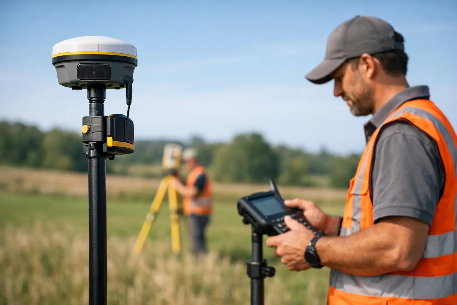
    RTK surveying works by combining satellite observations from two GNSS receivers. One receiver sits on a known point and acts as the base station. The other is the rover, which moves through the site collecting positions. Because both receivers are observing many of the same satellites at the same time, the system can compare what the rover sees against what the base sees.

    The base station already knows its true coordinates. It can therefore work out the errors affecting the GNSS signals at that moment, including satellite orbit uncertainty, clock errors, atmospheric delay, and some local effects. It then sends correction data to the rover in real time, usually by radio or mobile data connection.

    The rover uses those corrections to resolve its position much more precisely than it could on its own. Rather than relying only on a broad code-based position, RTK uses carrier phase measurements from the satellite signals. This is where the high accuracy comes from. The system is effectively measuring fractions of the signal wavelength and resolving integer ambiguities to refine the final position.

    That is the technical core of RTK. In practical terms, it means your rover is no longer guessing within a few metres. It is calculating a corrected position tied to a known reference, updated live as you work.

    The key components in an RTK workflow

    An RTK setup is straightforward on paper, but performance depends on each part of the chain working properly.

    Base station or correction source

    The correction source can be a local base station set up on site or a network RTK service delivered over mobile internet. A local base gives you direct control and can perform very well on contained sites. A network service uses multiple permanent reference stations and computes corrections across a wider area, which is often more convenient for mobile teams covering different locations.

    The right choice depends on site size, mobile coverage, required traceability, and whether your team is working repeatedly in the same area.

    Rover receiver

    The rover is the field unit used to record points, stake out coordinates, or collect topographic data. Modern rovers track multiple constellations such as GPS, GLONASS, Galileo, and BeiDou. More satellites generally improve reliability, especially around obstructions or during challenging sky conditions.

    Data link

    Corrections must reach the rover quickly and consistently. If that link drops, so does the quality of the RTK fix. UHF radio is common for local base-to-rover setups. NTRIP over 4G or 5G is common for network RTK or internet-connected base stations.

    Survey software and control

    The software manages coordinate systems, logging, quality checks, stake-out routines, and export. This matters more than many buyers expect. Good hardware with poor configuration can still produce poor outcomes.

    Why RTK is more accurate than standard GNSS

    Standalone GNSS calculates a position from satellite timing signals, but several error sources affect the result. Satellite clocks are not perfect. Orbits are predicted rather than absolute. Signals slow as they pass through the ionosphere and troposphere. Reflections from buildings, vehicles, and structures can introduce multipath.

    RTK improves this because the base station experiences nearly the same satellite and atmospheric conditions as the rover, provided the two are not too far apart. By comparing observations, the system removes much of the common error. The remaining challenge is resolving the carrier phase ambiguities correctly. Once fixed, the rover can report a highly precise position in real time.

    That is also why RTK performance is not just about owning a rover. Accuracy depends on baseline length, correction quality, satellite visibility, receiver capability, and operator practice.

    What accuracy can you expect?

    Under suitable conditions, RTK commonly delivers around 10 to 20 mm horizontal accuracy and 20 to 30 mm vertical accuracy, though this varies by equipment, environment, method, and quality control. Manufacturers may quote similar figures, but field conditions always matter more than brochure numbers.

    Open-sky sites with good satellite geometry and a stable correction link usually perform well. Tight urban corridors, steep cuttings, tree cover, heavy plant movement, or reflective surfaces can degrade results. Vertical accuracy is usually less forgiving than horizontal, which is important when setting levels, drainage falls, or finished surfaces.

    For that reason, professional users should think in terms of achievable site accuracy rather than ideal laboratory accuracy.

    Where RTK works well – and where it does not

    RTK is highly effective for topographic surveys, construction set-out, as-built capture, machine control support, ground control for drone surveying, utility mapping, and agricultural guidance. It is fast, efficient, and well suited to projects where teams need accurate coordinates immediately in the field.

    It is less effective where satellite visibility is poor or unstable. Dense woodland, urban canyons, tunnels, indoor spaces, and locations with severe multipath can all limit the ability to maintain a fixed solution. In these cases, users may need to switch methods, integrate total station workflows, or use post-processed techniques.

    This is one of the key trade-offs. RTK is quick and accurate, but it is still dependent on signal conditions. It is not a universal substitute for every survey instrument on every site.

    How does RTK surveying work on a live project?

    On a live project, the workflow usually starts with control. If using a local base, the base station is set over a known coordinate or established control point. If using a network correction service, the rover connects through the appropriate mountpoint and coordinate framework.

    The operator then initialises the rover, confirms satellite lock, and waits for a fixed RTK solution rather than a float solution. That distinction matters. A fixed solution means the carrier phase ambiguities have been resolved with confidence. A float solution is less certain and generally not suitable for precision work.

    Once fixed, the surveyor can begin recording points, checking features, or staking out design coordinates. Good practice includes regular checks against known control, monitoring precision indicators, and being alert to changes in signal quality. If the fix status drops, the operator should stop and verify rather than simply continue logging.

    For organisations running multiple field teams, this is where a supported workflow makes the difference. Equipment choice, correction service configuration, training, and data handling all affect whether RTK saves time or creates rework.

    Common reasons RTK results go wrong

    Most RTK problems are not caused by the concept itself. They come from setup, environment, or process.

    Using the wrong coordinate system is a common issue, particularly when moving between grid, local, and site calibration workflows. Poor base setup, unstable poles, inaccurate antenna heights, weak mobile coverage, and inadequate checks can all compromise results. Operators can also place too much trust in a fixed status without considering whether the broader survey control supports it.

    There is also a commercial point here. Buying capable GNSS hardware is only part of the decision. Teams also need training, technical support, and a workflow that fits the project environment. That is why many UK organisations work with providers such as LiDAR Tech UK that can support equipment supply, correction-enabled workflows, implementation, and field delivery rather than simply dispatching a box.

    RTK versus other high-accuracy methods

    RTK is often compared with PPK, static GNSS, and total station surveying. Each has a place.

    RTK is strongest when you need immediate coordinates on site. PPK can be advantageous where live corrections are unreliable but raw data can be processed afterwards. Static GNSS is better suited to longer occupation control work. Total stations remain essential where line of sight is available but satellite visibility is poor, or where extremely precise local measurement is required.

    For many projects, the best answer is not one method alone. It is a combined workflow built around the site constraints and required deliverable.

    If you are assessing RTK for operational use, the real question is not simply whether it works. It is whether the equipment, corrections, support, and survey method are aligned well enough to produce repeatable, defensible results when time and accuracy both matter.
  • Mobile LiDAR Scanner for Land Surveys

    Mobile LiDAR Scanner for Land Surveys

    A site that would take days to measure with total stations and GNSS alone can often be captured in a few hours with a mobile lidar scanner for land surveys. That difference matters when access is restricted, traffic management is costly, or a contractor is waiting on reliable topographic data to keep a programme moving.

    For professional buyers, the question is not whether mobile LiDAR is useful. It is where it fits, what level of accuracy is realistic, and whether the workflow stands up commercially. In land surveying, the value comes from faster coverage, denser spatial data and safer collection in environments where conventional methods become slow or inefficient.

    What a mobile LiDAR scanner for land surveys actually does

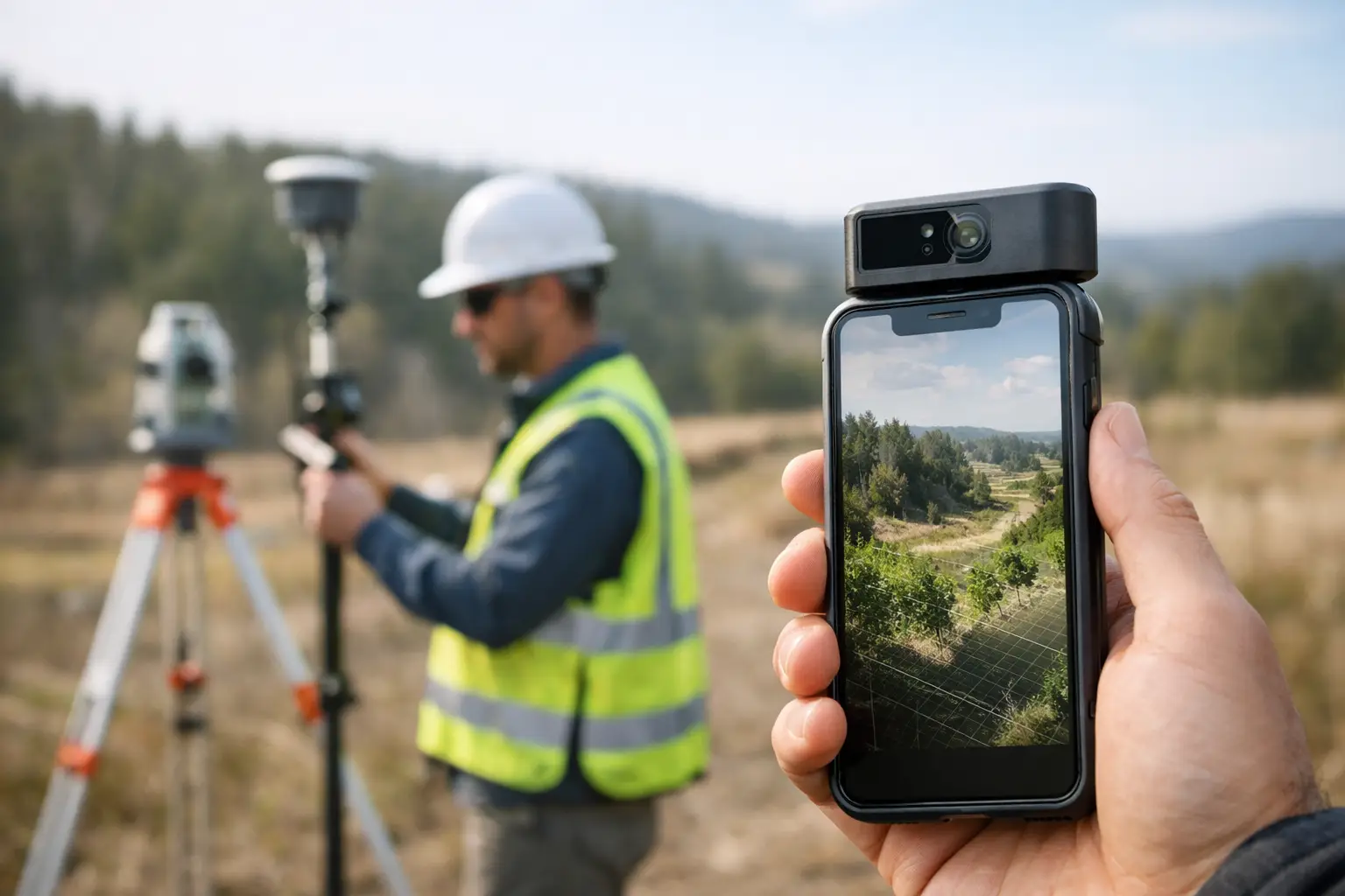
    A mobile LiDAR scanner records dense 3D point cloud data while the operator moves through the site. Depending on the system, that movement may be on foot, mounted on a vehicle, or integrated with a drone-based workflow. The scanner emits laser pulses, measures return times and builds a spatial model of terrain, structures, boundaries, corridors and surface features.

    In land surveying, this changes the field method. Instead of collecting one point at a time, the operator captures a continuous dataset across the whole environment. That is particularly useful on complex sites where retaining walls, embankments, vegetation edges, kerb lines, facades and service corridors all need to be represented in a single survey output.

    The commercial benefit is speed, but speed on its own is not enough. The real advantage is speed with traceable survey control, practical processing workflows and outputs that can support CAD, BIM, GIS or volumetric analysis.

    Where mobile LiDAR delivers the strongest return

    The best use cases are not always the largest sites. They are the sites where time on the ground is expensive, hazardous or operationally disruptive.

    Construction and civil engineering teams use mobile systems to capture existing conditions before design, monitor progress, document earthworks and verify built assets. Utilities teams use them along roads, substations and service routes where access windows are short and traditional methods can create bottlenecks. Infrastructure managers benefit when they need consistent corridor data with enough density to support clearance assessment, asset location and surface modelling.

    For topographic work, a mobile lidar scanner for land surveys is especially effective where the site contains a high volume of breaklines, level changes and hard detail. It can also help with stockpile measurement, drainage assessment, highway environments, quarry work and brownfield redevelopment.

    That said, not every project suits a mobile approach. If the brief is a very small area with a limited number of defined points, conventional survey may still be more efficient. Likewise, if the requirement is millimetre-level detail on specific installed components, static scanning or targeted total station work may be the better fit.

    Accuracy expectations in real survey conditions

    Accuracy is where buyers need clarity. Mobile LiDAR is not one single performance category. Results depend on the scanner, the GNSS environment, IMU quality, survey control, operator method and post-processing discipline.

    In open conditions with a strong positioning solution and proper control, mobile systems can achieve highly usable survey-grade results for many land and engineering applications. In dense urban streets, woodland, under bridges or beside tall structures, the positioning environment becomes more difficult. Drift, occlusion and degraded satellite visibility can affect the dataset if the workflow is not designed correctly.

    This is why specification sheets only tell part of the story. A stated accuracy figure is useful, but the more relevant question is whether the full workflow can achieve the tolerance your project requires. If the output is for feasibility mapping, route planning or general site modelling, mobile LiDAR may be ideal. If the output supports legal boundary definition, deformation monitoring or precise set-out control, additional methods and checks are likely to be necessary.

    Professional deployment means treating mobile LiDAR as part of a survey system, not as a standalone shortcut. Ground control, check points and sensible validation remain essential.

    Why control still matters

    Even with advanced SLAM and integrated GNSS, survey control provides the framework that turns fast capture into defensible output. It allows the point cloud to be tied into the required coordinate system, checked against known values and aligned with other datasets.

    For organisations managing repeated surveys across multiple sites, that consistency becomes even more important. Reliable control supports change detection, phased construction comparison and clean integration with existing mapping.

    Mobile LiDAR versus traditional methods

    The comparison should be practical rather than ideological. Total stations, GNSS rovers, static laser scanners, drones and mobile LiDAR all have a place. The right choice depends on terrain, detail, access and final deliverables.

    A total station remains excellent for precise discrete points, set-out and controlled feature capture. GNSS is efficient in open sky and ideal for many topographic tasks, but it becomes less effective under canopy or around built obstructions. Static laser scanning produces very high-detail data, though with more set-up positions and more time in the field. Drone LiDAR adds major value for larger areas, inaccessible ground and corridor mapping, but may involve airspace restrictions, permissions and weather limitations.

    Mobile LiDAR sits in the middle as a productivity tool for dense 3D capture over operational land. It is often the best answer when you need more detail than conventional point collection provides, but without the field time burden of repeated static set-ups.

    Choosing a mobile lidar scanner for land surveys

    Selection should start with job requirements, not with headline range or marketing claims. A buyer should assess the likely survey environment, expected tolerance, deliverable format and the capability of the team who will operate and process the data.

    Sensor quality matters, but so do positioning performance, software maturity and support. A scanner that captures quickly but creates slow, inconsistent processing is not efficient in real terms. Equally, a strong hardware platform without training and technical backup can leave a survey team underusing the equipment or introducing avoidable errors into production.

    For UK organisations, practical support is often the deciding factor. Buyers need to know how quickly they can get advice, calibration guidance, workflow help and, if required, project assistance. This is one reason many professional users prefer to work with suppliers that understand both the equipment and the survey outcomes expected on live projects.

    Questions worth asking before you buy

    Ask what coordinate workflows the system supports, how it performs in poor GNSS conditions, what quality control tools are available in software and how easily data exports into your existing CAD or GIS environment. It is also worth asking what level of training is included and whether there is access to processing support when workloads increase.

    The cheapest entry point is not always the lowest operating cost. If the system reduces revisits, shortens processing and produces dependable deliverables first time, it usually offers the better return.

    Processing, deliverables and operational reality

    Field capture is only half the job. The point cloud then needs to be registered, georeferenced, cleaned, classified and converted into usable outputs. Depending on the brief, that may include DTM generation, contours, cross-sections, measured linework, volumetric reports or 3D models.

    This is where many organisations underestimate the workflow. Dense data is valuable, but it also needs storage, computing capacity and a clear production method. If your team is set up for conventional topographic drafting only, moving into mobile LiDAR may require changes in software, training and quality assurance.

    Handled properly, though, the gain is significant. One well-executed capture can support multiple deliverables and reduce the need for return visits. It also creates a detailed site record that can be revisited digitally if additional measurements are needed later.

    Buy equipment or outsource the survey?

    That depends on survey frequency, staff capability and the commercial model of the business. If mobile LiDAR will be used regularly across infrastructure, development, utilities or asset programmes, owning the equipment can make strong financial sense. It gives the team control over deployment and can reduce dependence on subcontract availability.

    If usage is occasional or the organisation is still evaluating workflows, outsourced delivery may be the better route. It allows the business to test outputs, understand accuracy in its own operating context and assess return on investment before committing to capital purchase.

    Some buyers also take a hybrid route – using a specialist partner for initial projects while building internal capability over time. For firms that want both equipment access and operational support, LiDAR Tech UK works well because it combines supply, training and project delivery within the same geospatial offering.

    What good looks like on a live project

    A good mobile LiDAR survey is not just fast. It is planned around control, site constraints and deliverables from the start. The capture path makes sense, the positioning strategy reflects the environment, and the final dataset is checked against known values before issue.

    When that happens, mobile LiDAR becomes more than a data collection tool. It becomes a way to reduce site time, improve safety, increase detail and keep downstream design or construction decisions moving with fewer delays.

    The strongest results usually come from a simple principle: choose a mobile system because it suits the survey problem, not because it is the newest method. When the workflow matches the job, the technology earns its place very quickly.