
Category: Blog

  • A Professional Guide to LiDAR Data Capture

    A Professional Guide to LiDAR Data Capture

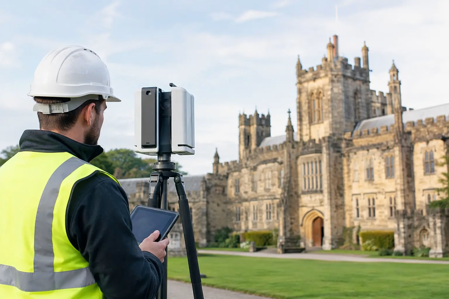
    A point cloud is only as valuable as the decisions made before the scanner is switched on. This guide to LiDAR data capture is intended for UK survey, construction and asset teams that need reliable, usable spatial data rather than a large file that creates more work in the office. The objective is to define the required output, select a capture method that suits the site, establish dependable control and maintain quality checks from fieldwork through to delivery.

    Start with the required deliverable

    LiDAR capture should begin with the question: what will the data be used for? A topographic survey, volume calculation, BIM model, highway corridor, asset inventory and heritage record each require a different balance of accuracy, density, coverage and classification.

    For example, a contractor checking cut and fill may need a georeferenced surface model delivered quickly. An engineering team producing a detailed design model may require more stringent control, defined feature extraction and CAD-ready linework. A facilities manager documenting plant rooms may prioritise complete coverage around equipment and clear imagery to support identification.

    Set the specification before mobilisation. It should identify the coordinate reference system, vertical datum, required accuracy, point density, deliverable formats, exclusions and tolerances. Agree whether the client needs raw point clouds, registered scans, classified data, a digital terrain model, orthomosaic, mesh, 3D model or drawing output. This avoids a common failure point: capturing a technically impressive dataset that is unsuitable for the intended workflow.

    Guide to LiDAR data capture: choose the right platform

    There is no single best LiDAR platform. The correct choice depends on the environment, access constraints, level of detail and acceptable survey duration.

    Mobile and handheld LiDAR

    Handheld and mobile LiDAR systems are effective for buildings, stockpiles, industrial facilities, streetscapes and complex sites where the operator can walk the required route. SLAM-based scanners can collect extensive data rapidly, including areas that are slow to cover with static scanning. They are particularly useful where access is intermittent or where teams need to capture progress information without disrupting site activity.

    The trade-off is that SLAM accuracy depends on the quality of the trajectory and the geometry of the environment. Long, featureless corridors, repetitive warehouse racking and open areas with few fixed features can increase drift risk. Closing loops, maintaining consistent walking speed, scanning from multiple directions and using surveyed control points will improve confidence in the final dataset.

    Static terrestrial laser scanning

    Static terrestrial scanners remain the preferred option where maximum local detail, repeatable accuracy and comprehensive line-of-sight coverage are required. They suit structural surveys, heritage documentation, plant rooms, façades and legal or engineering work where every critical feature must be defensible.

    This method takes longer in the field because each scanner position requires set-up and registration planning. However, it can be the right commercial choice when a missed detail or poorly controlled model would cause design delay, rework or access costs later in the project.

    UAV LiDAR

    Drone-based LiDAR is suited to larger sites, inaccessible terrain, transport corridors, quarries, forestry and utilities routes. It can capture terrain through light to moderate vegetation more effectively than image-based photogrammetry, depending on canopy density and the required ground return. It also reduces exposure to steep slopes, unstable ground and live operational areas.

    UAV LiDAR requires careful flight planning, appropriate permissions, site risk assessment and a realistic view of weather conditions. Wind, rain, low light for supporting imagery, battery management and airspace restrictions all affect productivity. The flight plan should provide sufficient overlap and a consistent height above ground, while the sensor configuration must match the target point density and vegetation conditions.

    Vehicle-mounted and hybrid workflows

    For roads, rail-adjacent assets and long linear networks, vehicle-mounted systems can collect data at a pace that walking or static scans cannot match. In many projects, a hybrid approach is more effective: UAV LiDAR for broad coverage, mobile scanning for ground-level detail, and static scans for critical structures or concealed areas.

    The benefit is not simply faster capture. Combining methods closes line-of-sight gaps and gives designers a more complete representation of the site. The drawback is added registration and processing discipline, so the control strategy must be shared across every platform.

    Establish survey control before collecting data

    Survey control is the backbone of professional LiDAR work. If control is weak, even a dense and visually convincing point cloud can be displaced, tilted or inconsistent with existing design data.

    Use established control where it is verified and suitable for the required accuracy. Where new control is needed, GNSS/RTK methods can provide efficient site coverage, while total station observations may be necessary where satellite visibility is limited or tighter local precision is required. Check the coordinate system and transformation parameters against the client’s project requirements rather than assuming a site grid or legacy drawing is correct.

    Ground control points and check points serve different purposes. Control points are used to constrain or georeference the dataset. Independent check points test the final result. Keep them separate where possible. A dataset that fits its own control points well has not necessarily demonstrated independent accuracy.

    For mobile LiDAR, establish visible, well-distributed targets where the workflow benefits from them. For UAV work, position control across the full site extent and consider height variation, not just plan position. Avoid placing all points along one boundary or in easy-to-access areas. Control needs to test the terrain and geometry that matter to the final deliverable.

    Plan the route, scan geometry and site access

    A reliable capture plan considers how the sensor will see every required surface. Walk the site before scanning where practical. Identify reflective materials, glass, water, narrow spaces, moving machinery, overhead obstructions, vegetation and areas where staff or public movement could affect the survey.

    For handheld LiDAR, plan a route with deliberate loop closures. Return to previously scanned areas, revisit key junctions and avoid making one long outward journey with no opportunity for the system to reconcile its position. In buildings, scan rooms in a sequence that creates strong overlap through doorways and corridors.

    For UAV LiDAR, define flight lines around terrain, obstructions and desired ground density. Consider whether cross-flight lines are needed to strengthen the trajectory solution or improve coverage on slopes. Maintain safe separation from people, structures and operational activity, and plan take-off and landing locations that do not compromise the survey or site safety.

    Do not treat site access as an administrative detail. A scan may need possession arrangements, permits, a banksman, traffic management, induction clearance or escort access. These constraints influence both platform choice and programme. Planning them early prevents rushed field decisions that reduce data quality.

    Capture with quality assurance built into the fieldwork

    Field checks are faster and cheaper than revisiting a site. Review coverage during collection rather than waiting until processing is complete. Confirm that critical surfaces are visible, control targets are captured clearly, and the scan route or flight path has not been interrupted by a battery issue, GNSS outage or unexpected restriction.

    Monitor positioning status throughout the survey. RTK corrections, satellite geometry, multipath, obstructions and loss of communications can affect georeferencing. If a correction service is unavailable or conditions deteriorate, record the issue and decide whether the work can continue under an alternative control method. Do not rely on a later software adjustment to resolve an unrecorded positioning problem.

    Keep clear field records. Note scanner settings, scan identifiers, control observations, weather, access limitations and any areas that could not be collected. These records support processing decisions and provide an audit trail when a client asks how an accuracy result was achieved.

    Process for the intended use, not just visual appeal

    Processing should preserve traceability from raw capture to deliverable. Register scans, apply control, inspect residuals and compare independent check points before exporting final data. Review the point cloud in sections as well as in 3D. Misalignments, duplicated surfaces and trajectory drift can be difficult to spot in a visually attractive overview.

    Classification and filtering need careful judgement. Ground filtering in vegetated terrain can remove valid terrain points or retain low vegetation. Noise reduction can improve readability but may also remove small features that matter to an asset survey. Agree the level of cleaning required and retain an archived source dataset where project requirements permit.

    Deliver data in formats that fit the client’s software and downstream tasks. This may include LAS or LAZ point clouds, E57 exchange files, RCP or RCS project formats, CAD drawings, terrain models, meshes or tabulated asset information. Include a concise report covering the capture method, coordinate system, control, checks completed, accuracy results and known limitations.

    When accuracy claims need context

    Quoted scanner accuracy is only one part of the final accuracy budget. Range, incidence angle, surface material, control quality, registration method, operator technique and processing settings can all influence the result. A manufacturer specification should therefore be treated as a component performance figure, not an automatic project outcome.

    For commercially sensitive work, define acceptance criteria in measurable terms. State whether accuracy is assessed against check points, surfaces, identifiable features or model elements. Specify the confidence level where appropriate and make clear which areas are outside scope. This protects both the survey team and the end user from assumptions that point-cloud density alone equals survey certainty.

    LiDAR Tech UK supports organisations that need to select, deploy and process professional LiDAR workflows, from equipment and positioning solutions through to survey deliverables. The most effective next step is to review a representative site, required outputs and accuracy tolerance before committing to a platform. That conversation usually reveals whether the priority is speed, detail, access, repeatability or a practical combination of all five.

  • GNSS Versus Total Station: Which Fits Your Site?

    GNSS Versus Total Station: Which Fits Your Site?

    A setting-out team is delayed because a retaining wall blocks satellite visibility. On another part of the same project, a surveyor spends hours moving a total station between control points across open ground. This is where the GNSS versus total station decision becomes operational rather than theoretical. Both technologies can deliver highly reliable survey data, but they work differently, carry different constraints and suit different stages of a project.

    For UK survey, construction and engineering teams, the best choice is rarely about replacing one instrument with another. It is about selecting the method that provides the required accuracy, coverage and productivity in the conditions actually present on site.

    GNSS versus total station: the practical difference

    A GNSS rover calculates its position from satellite signals, usually enhanced by RTK corrections from a local base station or network correction service. With a clear view of the sky and a dependable correction source, it can provide centimetre-level coordinates quickly over a large area. The operator can work independently, moving directly between points without establishing line of sight to an instrument.

    A total station measures angles and distances from a known occupied point to a prism, or in some cases to a reflectorless target. It works within a local coordinate framework and does not depend on satellite reception. Its principal requirement is clear line of sight between the instrument and the target.

    That difference shapes almost every field decision. GNSS is generally faster for open-site control, topographic work and large-area point collection. A total station remains highly effective where satellite signals are obstructed, where very precise local setting out is required, or where vertical and horizontal measurements must be maintained within a tightly controlled site grid.

    Accuracy: specify the result, not the instrument

    It is misleading to describe one technology as simply more accurate than the other. Accuracy depends on the measurement method, control arrangement, site environment, instrument quality, operator procedure and the tolerances required by the task.

    An RTK GNSS system commonly supports centimetre-level work when it has good satellite geometry, stable corrections and minimal multipath. Multipath occurs when signals reflect from nearby buildings, metalwork, vehicles or water before reaching the antenna. Tree canopy and urban obstruction can also reduce reliability or prevent a fixed solution altogether.

    A properly established total station can achieve millimetre-level angular and distance observations over appropriate ranges. This makes it a strong choice for structural set-out, steelwork, foundations, formwork, rail alignment, monitoring and detail survey in obstructed environments. The achievable site accuracy still depends on control quality, centring, prism handling, atmospheric conditions and sound checking procedures.

    The key question is not whether GNSS or a total station is accurate. It is whether the complete workflow can demonstrate the accuracy your deliverable requires. For an earthworks volume survey, centimetre-level GNSS may be entirely appropriate. For bolt positions, structural interfaces or machine alignment, a total station may be the more defensible method.

    Vertical accuracy needs particular attention

    Heights are often where teams discover the limits of an assumed workflow. GNSS ellipsoidal heights must be converted using an appropriate geoid model, and the resulting levels should be checked against known benchmarks. This is especially relevant when working to a project datum or where drainage, formation levels and construction tolerances are involved.

    Total stations measure vertical geometry directly from a known control point, but they too require careful instrument height, prism height and benchmark verification. Neither instrument removes the need for a controlled survey procedure.

    Where GNSS delivers the greatest return

    GNSS is particularly productive on open sites where points are spread over a wide area. The lack of line-of-sight requirements means one operative can collect observations efficiently without repeated instrument moves or a second person holding a prism.

    Typical applications include topographic surveys, site control extension, earthworks checks, stockpile volumes, utilities asset capture, agricultural mapping, boundary reconnaissance and as-built surveys across open developments. It is also useful for establishing georeferenced ground control for drone photogrammetry and LiDAR surveys.

    Its commercial advantage is coverage. A surveyor can walk directly to a required point, record an attributed observation and move on. On a highway corridor, solar farm, quarry, housing development or agricultural estate, that can materially reduce time on site.

    GNSS also supports an efficient digital workflow. Field software can display CAD linework, design points, background mapping and live positional guidance. For contractors, this can speed up setting out and reduce avoidable rework, provided the design data, coordinate reference system and datum have been checked before work begins.

    However, GNSS performance degrades in dense urban areas, beneath heavy canopy, close to tall structures and around reflective surfaces. A rover may still display a position, but the operator must assess solution status, estimated precision and the surrounding environment rather than accepting every coordinate at face value.

    Where a total station remains essential

    A total station is not legacy equipment. On many sites, it is the most controlled and efficient answer to the task.

    Use cases include basement works, enclosed compounds, internal surveys, rail environments, bridges, tunnels, industrial facilities and city-centre developments. It is also often the preferred instrument where satellite visibility changes through the day or where a local site grid must be maintained independently of GNSS corrections.

    For construction setting out, a robotic total station can provide substantial productivity gains. One operator can control the instrument remotely, locate points against design data and record as-built observations. The benefit is especially clear when setting out repeated locations with tight tolerances, such as pile caps, columns, kerbs, drainage runs or structural elements.

    Reflectorless measurement can also capture inaccessible features, though it should be applied with care. Surface material, angle of incidence, range and target definition affect reflectorless results. A prism remains the preferred option where the highest confidence is needed.

    The trade-off is field logistics. The total station must be set up over known control, oriented correctly and moved when line of sight is lost. On larger open sites, this can be slower than GNSS. It may also require a two-person team where robotic operation is not practical or available.

    Site conditions that should drive the choice

    Before mobilising, assess the site rather than defaulting to familiar equipment. Satellite visibility, control availability, required tolerances, point density, access and programme all matter.

    GNSS is usually the efficient first option when the site is open, coordinates are required over a broad area and centimetre-level results meet the specification. It is well suited to rapid capture and control tasks where the operator can maintain a fixed RTK solution and validate work against known points.

    A total station is generally the safer option where visibility to the sky is constrained, precise local geometry is critical or the work occurs beneath structures, near façades or inside buildings. It is also valuable where the client needs a clear observational chain back to established site control.

    For difficult ground, the answer is often both. GNSS can establish or extend control across open areas, support rapid topographic collection and georeference the wider project. A total station can then complete work around structures, under canopy and within tolerance-sensitive construction zones. This combined approach reduces the compromise inherent in relying on either method alone.

    Control, calibration and competence determine the outcome

    High-quality hardware does not compensate for weak control. Before setting out or collecting survey-grade data, confirm the coordinate system, transformation parameters, site datum and benchmark values. Check GNSS observations on independent known points. For a total station, verify collimation, compensator performance, tribrach condition and orientation against known control.

    Field checks should be planned, not treated as an afterthought. Re-observe selected points, compare against independent control and investigate differences beyond the project tolerance. Record instrument heights, prism heights, solution status and any environmental factors that could affect the result.

    Training matters just as much as specification. A team that understands RTK fix quality, geoid settings, localisations, resection quality and total station checks will produce more reliable data and identify problems before they affect construction or deliverables.

    Choosing equipment for your workflow

    When comparing GNSS and total station equipment, consider more than headline accuracy. Assess the correction service options, field software, controller usability, battery strategy, data export formats, support provision and integration with CAD, machine control, drones or LiDAR workflows.

    For organisations building an in-house capability, the strongest investment is often a connected survey workflow rather than an isolated instrument purchase. LiDAR Tech UK supports professional GNSS, RTK, LiDAR and drone systems alongside training, technical support and survey delivery, helping teams match the equipment and process to their actual project requirements.

    Start with the tolerance, site environment and required deliverable. A short technical review before purchase or mobilisation can prevent a far more expensive issue later: collecting data that looks complete but cannot support the decisions built on it.

  • Land Surveying Services for Accurate Site Data

    Land Surveying Services for Accurate Site Data

    A design team can only work as accurately as the existing-condition data placed beneath its drawings. A missed retaining wall, an incorrect invert level or a poorly defined boundary can trigger redesign, delay site operations and create avoidable commercial risk. Professional land surveying services establish a dependable spatial record before those decisions are made.

    For construction, civil engineering, utilities, land development and asset-management teams, the requirement is rarely just a set of points. The useful outcome is survey data at the right accuracy, in the right coordinate system and delivered in a format that supports the next stage of work. That may mean a CAD topographical survey for design, a georeferenced point cloud for modelling, an orthomosaic for site planning or verified levels for earthworks control.

    What land surveying services need to deliver

    A survey should answer a defined operational question. On a proposed development, this may be the position and level of surface features, buildings, boundaries, drainage covers, vegetation and changes in terrain. On an infrastructure corridor, the priority may shift to access routes, embankments, structures, clearances and condition information. For an estate or utility owner, asset identification and a repeatable record may be more valuable than a conventional drawing alone.

    The specification therefore matters as much as the equipment. Survey control, coordinate reference system, feature coding, linework detail, required tolerances and final file format should be agreed before fieldwork begins. A high-density scan is not automatically the right answer if the project requires a clear, controlled 2D base plan. Equally, a sparse topographical survey may be inadequate where designers need to understand complex façades, plant areas or irregular ground conditions.

    Typical deliverables include:

    • Topographical surveys in CAD-ready formats, with agreed layers, feature codes and levels.
    • Georeferenced point clouds for design coordination, measurement and 3D modelling.
    • Digital terrain models, contours and volume calculations for planning and earthworks.
    • Orthomosaic imagery and photogrammetric models for large sites and visual records.
    • Asset schedules and condition-related spatial data for inspection and maintenance planning.

    The most effective surveys combine these outputs only where they add value. More data can increase processing, storage and review time, so the goal is not maximum capture. It is usable information with known accuracy.

    Selecting the right survey method for the site

    Traditional GNSS and total-station workflows remain essential where controlled points, precise breaklines, detailed feature pickup and reliable level information are required. RTK GNSS is particularly effective in open environments, enabling survey teams to establish and capture coordinates efficiently against a suitable correction service or site control network.

    Its limitations must be recognised. Tree cover, tall structures, narrow streets, deep cuttings and reflective surfaces can affect satellite visibility or signal quality. In these locations, a survey method that relies solely on GNSS may not provide the required confidence. A competent survey plan accounts for obstructed areas, independent checks and the control needed to join different datasets accurately.

    Mobile LiDAR is well suited to collecting dense spatial data across complex sites. A handheld or vehicle-mounted system can rapidly capture building interiors, external structures, stockpiles, corridors and difficult terrain, producing a detailed point cloud that supports measurement and modelling. It can reduce time spent in exposed or inaccessible areas, particularly when paired with suitable control and a defined processing workflow.

    However, LiDAR does not remove the need for survey discipline. Point-cloud accuracy depends on sensor performance, trajectory quality, field technique, control strategy and registration. Dense data can also obscure the features a client actually needs unless it is classified, checked and converted into an agreed deliverable. For design purposes, the distinction between a visually convincing scan and an accurately controlled survey is commercially significant.

    Enterprise drones add another capability for larger sites, quarries, roof areas, embankments and inspections where ground access is slow or unsafe. Drone photogrammetry can provide high-resolution imagery, surface models and measurable orthomosaics. Drone LiDAR can improve vegetation penetration and terrain capture in certain environments. The appropriate option depends on ground cover, required accuracy, airspace constraints, weather, site permissions and the nature of the output.

    Control and accuracy are not optional extras

    A survey dataset is only dependable when its position can be understood and verified. This is why survey control is central to professional land surveying services. Control points connect field observations to a known reference framework and allow results from GNSS, total stations, LiDAR scanners and drone platforms to be checked against each other.

    For UK projects, teams should establish whether data needs to relate to the National Grid, Ordnance Datum Newlyn, a local grid or an existing project coordinate system. A mismatch can cause serious problems when incoming survey data is overlaid with design models, utility information or previous phases of work. It may be technically possible to transform data later, but doing so without clear documentation introduces unnecessary uncertainty.

    Accuracy requirements also vary by application. Early feasibility work may accept a lower level of detail than setting out, drainage design, legal boundary work or structural coordination. It is better to state the required tolerance and intended use at the outset than to assume that every survey is suitable for every downstream task.

    Quality assurance should include field checks, independent validation points, metadata on coordinate systems and a review of anomalies before issue. The final drawing or model should make clear what has been surveyed, what has been interpreted and which areas could not be observed safely or directly. This clarity helps designers and project managers make informed decisions rather than treating a survey as an infallible record.

    Planning surveys around operational risk

    The fastest field method is not always the most efficient project solution. A busy live site may require phased capture around vehicle movements, permits, inductions and restricted work zones. Rail, highways, utilities and industrial facilities often require additional access planning, safety controls and coordination with site representatives.

    Early communication prevents wasted mobilisation. Surveyors need to know the project boundary, access arrangements, known hazards, required outputs, programme deadlines and whether information such as existing drawings, control records or utility plans is available. The client also benefits from knowing where survey teams need clear access and whether vegetation, parked plant or stored materials could obstruct key areas.

    For repeat work, a structured capture approach can improve consistency. The same control framework, feature definitions and asset identifiers make it easier to compare sites, monitor change and integrate new data into established GIS, CAD or asset-management systems. This is particularly useful for local authorities, estates, contractors and infrastructure operators managing large portfolios.

    From field capture to usable design data

    Field capture is only one part of the service. Processing converts observations into information that engineering, planning and operational teams can use. This may involve point-cloud registration, noise reduction, classification, feature extraction, terrain modelling, CAD drafting, photogrammetric processing or conversion to client-specified formats.

    The right level of processing depends on the intended workflow. A modeller may need an E57 or LAS point cloud with control information. A civil engineer may need a DWG with 3D breaklines, spot levels and a clearly defined survey boundary. A project manager may require a visual site model and quantities. Supplying every possible file can create confusion, while supplying only a PDF can force costly rework.

    LiDAR Tech UK supports this end-to-end approach through professional field capture, LiDAR, GNSS and drone capability, processing expertise and outputs configured for practical project use. For clients building their own capacity, the same understanding also informs equipment selection, implementation and operator training.

    When to appoint a specialist survey provider

    Outsourced survey support is particularly valuable when deadlines are tight, sites are complex, specialist capture technology is needed or internal teams need independent data for design assurance. It is also a practical option for one-off projects where purchasing equipment, training operators and establishing processing procedures would not be commercially justified.

    When assessing a provider, look beyond the sensor specification. Ask how control will be established, what accuracy is achievable in the site conditions, how data will be checked, which formats will be issued and who will be available if the design team needs clarification. A clear scope, documented methodology and responsive technical contact are often more valuable than a headline capture rate.

    Accurate site information gives project teams a firmer basis for design, pricing and safe delivery. Start by defining the decision the survey must support, then specify the data, control and outputs needed to support it with confidence.

  • Best Drones for Surveying on Professional Sites

    Best Drones for Surveying on Professional Sites

    A drone survey is only as useful as the coordinates, imagery and point cloud it produces. The best drones for surveying are therefore not simply the aircraft with the longest flight time or highest camera resolution. They are professional platforms selected around the required accuracy, site conditions, deliverable and workflow – whether that is an orthomosaic for a planning application, CAD-ready topographic data, stockpile volumes or a classified LiDAR point cloud.

    For UK survey, construction and infrastructure teams, the right choice usually falls into one of three categories: a compact RTK photogrammetry drone for routine mapping, a larger payload platform for specialist sensors, or an integrated LiDAR system for terrain and asset capture. Each has a clear operational role.

    What separates a survey drone from a standard camera drone?

    Surveying requires repeatable positional control and data that can stand up to scrutiny. A consumer drone may capture attractive aerial imagery, but it is not designed around the same accuracy, reliability or data-management requirements as an enterprise system.

    A professional survey drone should support RTK positioning, ideally with a compatible network correction service or local base station. RTK improves the geotagging of each image or LiDAR measurement and reduces dependence on ground control points. Ground control remains good practice where verification, client specification or challenging conditions require it, but RTK can significantly reduce field time.

    The aircraft must also carry a camera or sensor suited to the job. A mechanical-shutter mapping camera avoids image distortion during flight, while a LiDAR payload captures direct range measurements and is better able to map through vegetation. Beyond the aircraft, assess flight-planning software, processing software, batteries, spare parts, operator training and technical support. These elements determine whether the system delivers productive survey days rather than isolated flights.

    Best drones for surveying by application

    DJI Mavic 3 Enterprise for efficient site mapping

    The DJI Mavic 3 Enterprise is a strong entry point for professional photogrammetry. Its compact format makes it practical for surveyors, small construction teams and asset managers who need to mobilise quickly across multiple sites. A mechanical-shutter wide-angle camera, RTK capability through the appropriate module, and long flight endurance make it well suited to topographic surveys, progress monitoring, stockpile measurement and roof or façade documentation.

    Its main advantage is efficiency. The aircraft can be deployed with minimal logistics, making it a sensible choice where teams are surveying smaller areas frequently and need a straightforward route from capture to orthomosaic, surface model or volume calculation.

    There are limits. Photogrammetry depends on visible ground texture and clear sightlines. Dense woodland, long grass and poorly textured surfaces can reduce the reliability of the resulting terrain model. The Mavic 3 Enterprise is excellent for mapped surfaces and visible features, but it is not a substitute for LiDAR where the ground is obscured.

    DJI Matrice 4E for higher-detail photogrammetry

    The DJI Matrice 4E is designed for professional mapping and surveying work that benefits from a more capable imaging platform. It combines a mapping-focused camera with additional imaging capability in a compact enterprise aircraft, providing a practical balance between detailed site capture and rapid deployment.

    This platform is particularly relevant for civil engineering schemes, detailed construction surveys, heritage recording and larger sites where image quality, coverage and operational confidence matter. RTK positioning supports accurate georeferencing, while automated flight planning helps maintain consistent overlap and capture geometry.

    For survey practices moving beyond occasional drone work, the Matrice 4E can provide a more scalable photogrammetry workflow than a basic compact aircraft. It remains a camera-led system, however. If the specification calls for bare-earth terrain beneath tree canopy, powerline corridor classification or dense 3D point-cloud capture, a LiDAR-equipped platform will generally be the better commercial decision.

    DJI Matrice 350 RTK with Zenmuse P1 for large-area mapping

    The DJI Matrice 350 RTK is the workhorse option for organisations that need payload flexibility, tougher operating capability and a platform that can support several survey disciplines. When paired with the Zenmuse P1 full-frame photogrammetry camera, it is a highly capable solution for large-area topographic mapping, quarry surveys, route corridors and high-resolution reality capture.

    The P1’s full-frame sensor and mechanical shutter enable efficient image capture at survey-grade ground sampling distances. Combined with RTK positioning and properly planned missions, it can produce detailed datasets for processing into orthomosaics, digital surface models, meshes and measured drawings.

    The trade-off is operational overhead. A Matrice 350 RTK system requires more transport capacity, more disciplined battery management and a higher initial investment than a compact drone. That investment is justified when the business needs reliable throughput, sensor interchangeability and the ability to deploy the same aircraft for mapping, thermal inspection or LiDAR work.

    DJI Matrice 350 RTK with Zenmuse L2 for LiDAR surveying

    For sites where vegetation, complex structures or variable lighting make image-based methods less dependable, the Matrice 350 RTK with Zenmuse L2 is among the best drone combinations for surveying. The L2 integrates LiDAR, an RGB mapping camera and an IMU to generate dense georeferenced point clouds while recording imagery for colourisation and contextual interpretation.

    This configuration is well suited to woodland terrain modelling, rail and highway corridors, utility routes, embankments, quarry faces, flood-risk studies and asset surveys. LiDAR can record returns through gaps in vegetation, allowing ground classification to produce a more realistic bare-earth model than photogrammetry alone in suitable conditions.

    LiDAR does not remove the need for survey control or quality assurance. Point-cloud accuracy depends on GNSS corrections, IMU performance, flight settings, calibration, control checks and processing discipline. It also creates a more specialist workflow: operators must understand point density, overlap, strip alignment, classification and the difference between a visually impressive cloud and a defensible survey deliverable.

    RTK, PPK and ground control: choose the accuracy workflow first

    It is tempting to specify a drone around camera resolution, but the accuracy workflow should be agreed before selecting the aircraft. RTK drones receive real-time corrections during flight, typically through a network correction service or base station. This is efficient and provides high-quality image geotags, provided correction coverage is stable.

    PPK processing applies corrections after the flight and can be useful where live communications are unreliable. In either case, independent checkpoints should be used to verify the finished dataset. For high-consequence engineering work, project specifications may also require a defined ground-control layout and documented accuracy report.

    The achievable result depends on more than RTK. Flight height, image overlap, camera calibration, terrain, control quality and processing settings all influence the final model. A claim of centimetre-level accuracy should always be tested against independently surveyed checkpoints rather than assumed from the equipment specification.

    How to select the right system for your operation

    Start with the deliverable. If clients mainly require orthomosaics, cut-and-fill calculations and progress reporting on open sites, an RTK photogrammetry drone such as the Mavic 3 Enterprise or Matrice 4E may be the most commercially efficient option. If work regularly covers large sites or requires very detailed imagery, the Matrice 350 RTK with P1 offers greater capability.

    If the business needs ground models beneath vegetation, dense corridor data or detailed 3D asset point clouds, specify LiDAR from the outset. A Matrice 350 RTK and Zenmuse L2 package has a higher purchase cost, but it can reduce field exposure and capture time on projects where conventional observation or image-only processing would be slow, incomplete or unsafe.

    Also consider operational resilience. Battery availability, a suitable RTK correction method, CAA-compliant operating procedures, payload insurance, training and processing capacity should be budgeted alongside the aircraft. A well-supported compact system often generates more value than an advanced platform without a clear workflow or trained operator.

    For organisations evaluating a purchase, a demonstration using a representative site and a defined output is more useful than a generic flight display. LiDAR Tech UK can help match the aircraft, positioning method, sensor and processing route to the required survey deliverable. The most effective investment is the one that produces verified data at the required accuracy, safely and consistently, on the jobs your team actually wins.

  • DJI Matrice 350 Review for UK Survey Teams

    DJI Matrice 350 Review for UK Survey Teams

    A professional drone has to earn its place in the vehicle. For survey, inspection and asset-management teams, that means more than impressive flight footage. It must carry the right sensor, maintain positional confidence, cope with changeable weather and return usable data without creating a difficult processing workflow. This DJI Matrice 350 review considers whether DJI’s enterprise platform meets those operational requirements for UK organisations.

    The Matrice 350 RTK, often referred to as the M350 RTK, is designed as a flexible airframe rather than a single-purpose survey drone. It supports DJI Enterprise payloads including the Zenmuse L2 LiDAR and RGB mapping sensor, Zenmuse P1 full-frame photogrammetry camera, H20 Series inspection payloads and thermal cameras. That flexibility is its principal strength, but it also means buyers need to define their workflow before selecting the aircraft and sensor package.

    DJI Matrice 350 review: what it delivers in the field

    The M350 RTK is built for repeatable commercial operations. Its quoted maximum flight time of up to 55 minutes is achieved under favourable conditions with an appropriate payload, rather than in every working scenario. Even so, it represents a meaningful improvement in productive flying time for wide-area mapping and extended inspection tasks.

    In practice, wind, temperature, payload weight, flight pattern and battery condition all affect endurance. A LiDAR mission flown at a controlled speed and height will produce a different result from a close-range bridge inspection involving frequent manoeuvres and hovering. Professional teams should plan missions around usable on-site endurance, safe battery reserve and the time required to change batteries, rather than treating the headline figure as a guaranteed flight duration.

    The dual TB65 battery system is well suited to field operations. Batteries can be changed without shutting the aircraft down, allowing crews to maintain workflow continuity between sorties. DJI rates the TB65 batteries for up to 400 charge cycles, which may reduce long-term operating costs for frequent users, provided charging, storage and battery-health procedures are managed properly.

    The aircraft also carries an IP55 protection rating. This does not make it a drone for unrestricted operation in rain, but it gives inspection and survey teams more confidence when working in the damp, dusty and variable conditions common on UK sites. The M350 RTK is a considerably more appropriate platform for demanding operational environments than a lightweight prosumer aircraft.

    Flight safety and control confidence

    The Matrice 350 RTK combines six-directional sensing and positioning with a low-light FPV camera to improve situational awareness. For work near structures, vegetation, pylons or industrial assets, these systems are valuable safeguards. They are not a substitute for competent planning, visual observation or a properly defined flight boundary.

    Its wind-resistance capability, enterprise controller and transmission system support confident operation across larger sites. That matters on linear projects, quarry surveys, large estates and infrastructure corridors, where a short communications range or marginal aircraft stability can slow progress quickly.

    For UK operators, the aircraft must still be deployed within the relevant CAA operating framework, site permissions and risk assessment. The M350 RTK’s capability does not remove the need for appropriate operational authorisation, airspace checks, trained personnel or a clear method statement.

    Payload choice determines survey value

    The airframe itself is only half of the purchase decision. The quality, speed and suitability of the final deliverable are determined largely by the payload and the data workflow behind it.

    For photogrammetry, the Zenmuse P1 is the natural choice for high-resolution RGB capture. Its full-frame sensor and mechanical shutter are designed for efficient mapping missions, producing imagery suitable for orthomosaics, point clouds, digital surface models and textured 3D models. It is particularly effective for construction progress records, stockpile calculations, land surveys and site documentation where clean visual detail is required.

    The Zenmuse L2 changes the proposition for sites with dense vegetation, complex ground form or a need for direct point-cloud capture. Combining LiDAR, an RGB mapping camera and an integrated IMU, it enables teams to acquire georeferenced laser-scanning data from the air. Forestry, utilities, rail corridors, earthworks and topographic surveys can benefit where photogrammetry alone struggles to identify ground through canopy or where consistent geometry is more valuable than photographic texture.

    For inspections, an H20 Series payload can combine zoom, wide-angle and thermal imaging in one mission platform. This is useful for roofs, façades, solar arrays, transmission assets, industrial plant and inaccessible structures. The M350 RTK can therefore support a mixed fleet requirement, with one aircraft configured for mapping on one day and asset inspection on the next.

    That versatility is commercially attractive, but there is a trade-off. A dedicated single-sensor system can be simpler to deploy and easier for occasional users to understand. The M350 RTK makes most sense when an organisation genuinely needs multiple payload options, expects regular operations or wants to standardise around an enterprise drone ecosystem.

    RTK positioning and data accuracy

    The integrated RTK module is a major benefit for geospatial work. It supports high-accuracy positioning during flight and can reduce the number of ground control points needed for many projects. This can shorten field time significantly, particularly on large, inaccessible or hazardous sites.

    RTK should not be confused with a guarantee of survey-grade deliverables in every circumstance. Final accuracy depends on the payload, flight planning, GNSS correction quality, terrain, image overlap or LiDAR settings, processing software and independent validation. Check points remain good practice where a defensible accuracy statement is required.

    For organisations using a local base station, network RTK correction service or PPK workflow, the M350 RTK can fit into established GNSS processes. The key is consistency. Survey teams should agree their coordinate reference system, geoid model, correction source and quality-control method before the first production mission. A technically capable aircraft cannot correct a poorly managed spatial reference framework.

    Operational benefits for UK organisations

    The strongest case for the M350 RTK is not simply that it flies for longer or carries better cameras. It is that it can reduce exposure to risk and compress the time between site capture and usable information.

    On a construction project, the platform can support regular topographic updates, volumetric measurements and progress imagery without repeatedly mobilising a large field crew. For utilities and infrastructure managers, it can collect close visual, thermal or LiDAR data while keeping personnel away from difficult access points. In forestry and environmental work, LiDAR payloads can help build a more detailed understanding of terrain and vegetation structure across extensive areas.

    Its transport case, enterprise batteries and payload change process also suit teams moving between sites. The aircraft is not compact in the way a small mapping drone is, but it is designed to be deployed as working equipment. For organisations carrying out planned weekly operations, that is often more valuable than minimum size.

    Limitations to consider before buying

    The M350 RTK is a premium enterprise system, and the true investment extends beyond the airframe. Payloads, spare batteries, charging equipment, RTK corrections, processing software, training, insurance and maintenance all need to be included in the budget. A low entry price is not the right comparison if the required sensor, support package and data-processing capability are missing.

    There is also a skills requirement. Flying the aircraft safely is only one element. Teams need confidence in mission planning, sensor settings, control surveys, data management and quality assurance. LiDAR and photogrammetry can generate substantial data volumes, so storage, workstation performance and processing turnaround should be assessed alongside field productivity.

    For straightforward roof surveys, small-area visual documentation or occasional marketing imagery, the M350 RTK may be more capability than necessary. A smaller enterprise drone can be quicker to transport and more cost-effective. Conversely, where one aircraft must support LiDAR, photogrammetry and inspection payloads with dependable endurance, the M350 RTK is a compelling platform.

    Is the DJI Matrice 350 RTK the right investment?

    The DJI Matrice 350 RTK is a serious operational drone for organisations that require more than imagery. Its weather-aware enterprise design, dual-battery workflow, integrated RTK capability and broad payload support make it well suited to professional survey, mapping and inspection programmes.

    Its value is highest when the aircraft is selected as part of a complete workflow: a suitable sensor, reliable correction service, trained operators and a clear route from raw capture to CAD-ready, model-ready or inspection-ready outputs. LiDAR Tech UK can help assess that workflow before purchase, so the chosen platform is matched to the accuracy, deliverables and operational demands of the work ahead.

    The most useful next step is to start with a representative project. Define the site conditions, expected accuracy, required output and turnaround time, then select the M350 RTK payload configuration against those requirements rather than the specification sheet alone.

  • How to Set Up a GNSS Base for Reliable RTK

    How to Set Up a GNSS Base for Reliable RTK

    A GNSS base is only as reliable as the control behind it. A high-specification rover can still produce poor positions if the base has been placed beneath obstructions, assigned the wrong coordinate system or configured with an incorrect antenna height. Knowing how to set up GNSS base equipment correctly is therefore fundamental to producing repeatable RTK results for setting out, topographic surveys, machine control and asset capture.

    For UK projects, the objective is not simply to achieve a fixed solution. It is to achieve a fixed solution that agrees with the required site grid, datum and level reference, and that can be verified throughout the working day.

    Start with the required survey control

    Before erecting the tripod, establish what the delivered data must match. This is particularly important where a project combines GNSS observations with total station work, existing design models, OS mapping or client-issued control.

    Confirm the horizontal datum and coordinate system, the vertical datum and geoid model, and whether the project uses a local site calibration. A base broadcasting ETRS89 positions while the rover is expected to deliver OSGB36 National Grid coordinates will introduce a consistent but potentially significant discrepancy. Likewise, ellipsoidal heights are not interchangeable with orthometric levels used for construction and drainage work.

    If verified control marks are available, occupy one of them. This provides the strongest basis for a local RTK setup because the base coordinate is known rather than estimated. Use the published coordinate values exactly as supplied, including the correct unit and coordinate order. Check whether heights refer to the ground mark, a reference point or an antenna reference point.

    Where no established control exists, an averaged autonomous position can support lower-risk work such as rapid mapping, volume estimates or initial site reconnaissance. It should not be treated as permanent survey control. The resulting coordinates may shift between sessions and will not necessarily agree with other survey datasets.

    Choose a base location that protects signal quality

    The best base location is stable, open to the sky and representative of the working area. A permanent survey pillar, a sound control point or a securely planted tripod on firm ground is preferable to a pavement edge, temporary compound surface or anything likely to move during the survey.

    Keep the antenna clear of trees, cranes, buildings, metal cladding and parked plant. These features obstruct satellite signals and can cause multipath, where reflected signals reach the antenna after the direct signal. Multipath can reduce repeatability even when the receiver reports an RTK fixed status.

    A clear horizon is valuable, but practical site conditions often require compromise. If the only viable point has partial obstruction, identify the affected directions and test the rover at the extremities of the intended survey area. A base on high ground may provide better radio coverage, but only if it remains secure and does not force unsafe access or expose equipment to site traffic.

    For longer occupations, protect the setup from accidental disturbance. Use a sturdy tripod, fully seat its feet and mark the position if the base needs to be re-established later. On active construction sites, barriers and clear communication with site management are often as important as receiver settings.

    How to set up GNSS base hardware accurately

    Mount the GNSS antenna or integrated receiver on a tribrach and tripod, then centre it precisely over the control mark. Use the optical plummet where available and level the tribrach before entering any coordinates. Integrated receiver systems with tilt compensation can make field work faster, but the base itself should still be level and centred unless the manufacturer specifically supports an alternative method.

    Measure the antenna height carefully. This is one of the most common sources of avoidable error. Receiver software may ask for a slant height, vertical height or a measurement to a specific antenna reference point. Select the measurement method that matches the equipment and record it in the survey notes.

    Do not assume a tape measurement is correct because it was taken once. Measure the height twice from different directions and compare the values. If the readings disagree, resolve the reason before starting the broadcast. A few millimetres of error at the base can directly affect rover elevations across the site.

    Enter the known base coordinates, select the correct datum, projection and geoid, and allow the receiver to initialise fully. If operating on a local grid, load the approved localisation or calibration file rather than attempting to recreate parameters from memory. A properly documented configuration is essential where multiple crews or return visits are involved.

    Configure the correction link

    The base must send corrections to the rover through either a UHF radio link or an internet-based NTRIP connection. The right method depends on site geography, communication infrastructure, required range and project operating model.

    UHF is often effective on contained sites where mobile coverage is poor or corrections must remain independent of an external network. Set the same radio protocol, frequency, channel spacing and data rate on both base and rover. Radio power should be appropriate to the required coverage, not automatically set to maximum. Higher output can improve range, but it consumes more power and must comply with applicable UK radio licensing and frequency requirements.

    An NTRIP setup can be useful where a stable internet connection is available and teams need corrections across dispersed locations. The base requires a reliable mobile data connection and an NTRIP caster or correction service configuration. Confirm that the mountpoint, format and credentials are correctly entered, then verify that correction age remains low at the rover.

    In either case, match the correction message format to the rover capability. RTCM is the common choice for modern multi-constellation systems, but the selected version and enabled constellations must be compatible across the workflow. GPS, Galileo, GLONASS and BeiDou observations can improve availability in challenging environments, provided both units are configured consistently.

    Initialise the rover and check the result

    At the rover, connect to the base correction stream and wait for an RTK fixed solution. Check more than the word “fixed”. Review correction age, satellite count, PDOP, radio signal or internet stability, and reported horizontal and vertical precision. A fixed solution with high correction age or intermittent communications should be investigated before work starts.

    The first practical quality-control test is to measure a second known point. Occupy it for long enough to obtain stable readings, then compare the observed position and level against the published values. Repeat the observation after moving away and returning to the point. This confirms that the base coordinate, antenna height, localisation and correction link are all working together.

    For engineering work, establish project tolerances before deciding what constitutes an acceptable check. A general topographic survey may permit a different tolerance from kerb setting out, structural works or as-built verification. Record the observed residuals, time, receiver details and correction method so results remain defensible if queried later.

    Maintain control throughout the day

    A satisfactory start-up check does not remove the need for ongoing verification. Re-check a known point after breaks, after moving the base, following a power interruption, and before issuing final data. If the check changes unexpectedly, stop collecting critical observations until the source has been identified.

    Common causes include a disturbed tripod, an incorrect antenna-height entry after restarting the controller, a changed coordinate system, radio interference or a rover that has reverted from fixed to float. Tree canopy and changing satellite geometry can also affect field performance, particularly in urban corridors, woodland and steep-sided sites.

    Keep concise field records: base point ID, coordinate source, antenna height and measurement method, radio or NTRIP settings, start and finish times, and check-point results. These notes allow a survey team to reproduce the setup, support QA procedures and quickly isolate issues when data does not align.

    For teams deploying RTK systems across varied UK sites, LiDAR Tech UK can assist with receiver configuration, site workflows and training aligned to the required survey output. The most productive setup is the one that is not only fast to deploy, but also straightforward to validate and repeat.

    A GNSS base should be treated as the control centre of the survey, not merely a transmitter on a tripod. Give the coordinate reference, antenna height and independent checks the same attention as the rover measurement, and your RTK data will carry the consistency needed for confident decisions on site.

  • Drone Mapping Versus Ground Survey: Which Fits?

    Drone Mapping Versus Ground Survey: Which Fits?

    A 40-hectare construction site does not always need weeks of boots-on-the-ground measurement. Equally, a drone flight cannot establish a reliable kerb line beneath dense tree cover or set out structural elements to millimetre-level tolerances. The decision between drone mapping versus ground survey should be based on the required accuracy, site conditions, deliverables and programme – not on which technology appears quicker at first glance.

    For most professional projects, the strongest answer is not drone or ground survey. It is a planned workflow that uses each method where it produces the most dependable result.

    Drone Mapping Versus Ground Survey: The Core Difference

    Drone mapping captures a large volume of spatial data from above. Using photogrammetry or drone-mounted LiDAR, teams can produce orthomosaics, point clouds, surface models, contours, stockpile volumes and 3D meshes across substantial areas in a short field visit. This makes it particularly effective for topographic mapping, progress monitoring, quarry surveys, land management and inaccessible asset inspections.

    Ground survey measures selected points, lines and features directly from the site. GNSS/RTK rovers, total stations, terrestrial LiDAR scanners and conventional levelling techniques give surveyors close control over feature capture and coordinate quality. They remain the preferred choice where detail is obscured from the air, where levels must meet a tight tolerance, or where legal boundaries and setting-out decisions are involved.

    The difference is therefore not simply speed versus precision. Both can be highly accurate when specified, controlled and processed correctly. The real distinction is data density and perspective. A drone rapidly provides broad-area coverage and visual context. A ground crew can verify critical features at source and work around obstructions that aerial sensors cannot see through.

    Accuracy Depends on Control, Not the Platform Alone

    Claims that drones are inaccurate, or that ground methods are automatically more accurate, are both too simplistic. Accuracy depends on the sensor, flight or observation plan, coordinate reference system, site control, processing method and quality assurance.

    For drone photogrammetry, RTK positioning can improve image geotagging and reduce the number of ground control points needed. It does not remove the need for validation. Independently surveyed checkpoints are still the sound way to confirm that an orthomosaic or terrain model meets the required horizontal and vertical accuracy. Ground control is especially valuable on sites with changing elevation, weak GNSS conditions or a requirement for defensible survey reporting.

    Drone LiDAR can provide useful topographic data where photogrammetry struggles, particularly around partial vegetation cover. However, its results still need suitable GNSS and IMU performance, careful trajectory processing and ground checks. Dense woodland, steep terrain and poor satellite visibility can all affect the final dataset.

    Ground survey offers more direct control for individual features. A total station can capture a precise breakline, drainage channel, building corner or rail feature without relying on pixel matching or aerial visibility. Digital levels remain appropriate when transferring critical levels across a project. Where a specification calls for centimetre-level terrain data across a wide site, a controlled drone survey may be suitable. Where it calls for millimetre-level setting out or precise structural monitoring, conventional ground methods should lead.

    Coverage and Productivity on Large Sites

    This is where drone mapping has a clear operational advantage. A surveyor can collect imagery or LiDAR across areas that would take a ground crew many hours or days to traverse, particularly on rough, muddy or recently disturbed ground. The output is also richer than a sparse set of measured points: project teams receive a visual record of the site alongside measurable spatial data.

    For earthworks, landfill cells, aggregates, highways corridors and development sites, regular drone flights can establish a repeatable record of change. Comparing successive surface models helps quantify cut and fill, track stockpile movement and identify whether construction is progressing against the intended programme.

    Ground survey becomes comparatively time-consuming when the brief requires full coverage over a large open area. It is still highly effective for targeted work, such as capturing service chambers, kerbs, building thresholds, drainage inverts and other defined features. The productivity question is not whether a crew can measure these points, but whether it is commercially sensible to measure every metre of a site manually when aerial capture can provide the wider terrain model.

    Access, Safety and Site Constraints

    Aerial survey reduces exposure to hazards. It can capture roofs, unstable slopes, water margins, quarries, rail-adjacent areas and restricted zones without placing an operative directly in the hazard area. This is a significant benefit, but it does not mean drone operations are risk-free.

    UK drone work requires appropriate planning around airspace, people, structures, weather, take-off and landing areas, and the specific operating environment. Wind, rain, low light and poor visibility can delay missions. A site near an airport, prison, critical infrastructure location or busy public area may require additional permissions, coordination or a different survey approach.

    Ground survey can continue in places where a drone cannot operate, but it introduces its own risks. Survey teams may face moving plant, uneven ground, traffic, water, confined spaces or difficult access. A sensible method statement considers the hazards of both approaches rather than assuming the airborne option is automatically safer.

    Vegetation, Obstructions and Feature Visibility

    Photogrammetry works best when the ground surface is visible from above. Long grass, crops, scrub, standing water, shadows and reflective materials can reduce the quality of an aerial terrain model. It may produce an attractive image while failing to represent the true ground level beneath vegetation.

    LiDAR is often the stronger drone option for corridors and woodland because laser pulses can return from gaps in the canopy. Even then, dense vegetation is not a guarantee of complete ground penetration. Classification needs experienced processing, and critical areas should be checked on the ground.

    Ground survey is the practical answer for hidden detail. Surveyors can measure beneath canopies, around building overhangs and inside areas where line-of-sight permits. Terrestrial LiDAR can also capture façades, plant rooms, structures and complex built assets with far greater detail than an overhead drone flight. For many sites, drone data maps the open ground while targeted ground observations close the gaps.

    Deliverables Should Drive the Method

    Before selecting equipment or appointing a survey provider, define the output that the design, commercial or asset-management team actually needs. A planning team may need a current orthomosaic and a broad topographic model. A quantity surveyor may need a verified stockpile volume. A civil engineer may need CAD-ready breaklines, spot levels and drainage features. An asset manager may need a colourised point cloud or inspection imagery.

    Drone mapping is well suited to large-area deliverables: orthomosaics, digital surface models, digital terrain models, contours, volumetrics and visual 3D models. Ground survey is typically better for detailed CAD feature capture, setting out, monitoring points and surveys of obscured or internally located assets.

    The final deliverable must also be understood in context. A high-density point cloud is not automatically a usable design model. It needs the correct coordinate system, filtering, classification, validation and export format. The value lies in data that can be used confidently in CAD, GIS, BIM or engineering workflows, not simply in collecting more points.

    Cost: Compare the Whole Workflow

    A drone survey can reduce field time substantially, but the cheapest flight is not always the lowest-cost survey. Costs can rise when control is inadequate, processing is poorly specified, access planning is overlooked or the required outputs have to be recreated manually afterwards.

    Likewise, sending a ground crew to capture a few hundred points may be economical for a compact site with a clear, defined brief. It becomes less attractive when the site is extensive, hazardous or requires repeat measurement every fortnight. The right comparison includes mobilisation, field time, permissions, control, processing, quality checks, deliverable preparation and the cost of rework.

    Organisations purchasing their own systems should also consider training, operational procedures, correction services, processing software and technical support. Enterprise drone and GNSS equipment performs best as part of a complete survey workflow, not as an isolated hardware purchase.

    A Combined Survey Workflow Usually Produces the Best Result

    For many UK construction, infrastructure and land projects, a hybrid method is the most commercially sound approach. Establish survey control with GNSS, total station or levelling methods. Use the drone to capture efficient site-wide imagery or LiDAR. Validate the aerial model against independent checkpoints, then supplement hidden, critical or tolerance-sensitive features with ground observations.

    This approach provides broad coverage without losing confidence in key measurements. It also gives project teams a current visual record while supplying survey-grade data for design and commercial decisions. The method can be repeated throughout the programme, creating consistent datasets rather than disconnected site snapshots.

    LiDAR Tech UK supports this type of workflow through professional drone, GNSS/RTK and LiDAR solutions, backed by technical guidance, training and survey data services. The right starting point is a clear definition of the decision the data needs to support, the tolerance that decision demands and the conditions found on site. Once those are known, the appropriate balance between aerial and ground capture becomes much easier to specify.

  • LiDAR Versus Photogrammetry Surveying

    LiDAR Versus Photogrammetry Surveying

    When a project team asks for a topographic survey, stockpile calculation or site model, the real question is often not whether to capture data digitally. It is whether LiDAR versus photogrammetry surveying is the better fit for the job. That decision affects accuracy, field time, processing effort, site access, and ultimately whether the final dataset is genuinely useful for design, construction or asset management.

    Both methods are proven. Both can produce detailed deliverables. But they work in very different ways, and the right choice depends on the environment, the required outputs and the level of certainty your project demands.

    LiDAR versus photogrammetry surveying – what is the difference?

    LiDAR measures distance directly using laser pulses. A scanner, whether terrestrial, mobile or drone-mounted, records millions of points and creates a dense 3D point cloud. Because it is an active sensor, it does not rely on ambient light in the same way a camera-based workflow does.

    Photogrammetry uses overlapping images to reconstruct geometry. Specialist software identifies common points across multiple photographs and calculates their position in 3D space. The result can include point clouds, orthomosaics, textured meshes and surface models.

    For many buyers, the practical distinction is straightforward. LiDAR captures shape by measuring it. Photogrammetry estimates shape by matching imagery. Both approaches can achieve strong results, but one may be more dependable than the other depending on vegetation, texture, lighting and the amount of geometric complexity present on site.

    Where LiDAR has the advantage

    LiDAR is often the stronger choice where geometry matters more than visual appearance. On infrastructure corridors, construction sites, rail environments, quarries and complex industrial assets, laser scanning can deliver highly consistent spatial data with less dependence on surface texture.

    It also performs well in low-texture environments where photogrammetry can struggle. A concrete wall, a uniform road surface or repetitive structural elements may not provide enough visual detail for stable image matching. LiDAR does not have the same limitation because it is recording range directly.

    Vegetation is another key factor. If the requirement is to model the ground beneath tree cover, LiDAR generally has a clear operational advantage. Depending on the sensor, platform and survey design, laser pulses can produce returns from vegetation and from the ground below, making it possible to classify terrain more effectively than with image-only methods.

    This matters in forestry, utilities, land development and flood-risk work, where a surface model of the canopy is not enough. If your team needs a more reliable terrain representation through partial cover, LiDAR is usually the safer technical choice.

    Where photogrammetry makes sense

    Photogrammetry remains highly effective for many commercial surveying tasks, particularly where visual context is valuable and surface visibility is good. For roofs, façades, earthworks, open sites and heritage documentation, image-based capture can provide detailed and visually rich outputs.

    It is also well suited to clients who need orthomosaics, inspection imagery or textured 3D models as part of the deliverable, not just geometry. A well-planned drone photogrammetry survey can cover large areas efficiently and produce outputs that are easy for non-specialist stakeholders to interpret.

    On straightforward open-ground sites, photogrammetry can be a cost-effective option when supported by proper ground control and a disciplined processing workflow. If the project tolerance allows it and the surface conditions are favourable, it can provide the required data without the additional hardware cost associated with LiDAR payloads.

    Accuracy is not just about the sensor

    One of the most common mistakes in LiDAR versus photogrammetry surveying comparisons is to treat accuracy as a headline figure taken from a brochure. In practice, survey accuracy depends on the entire workflow.

    Control strategy, GNSS performance, RTK or PPK correction quality, flight planning, scan geometry, overlap, calibration, target placement and processing discipline all influence the result. A poorly controlled LiDAR survey can underperform. A well-executed photogrammetry project can exceed expectations.

    That said, LiDAR usually offers a more predictable route to dependable geometry on complex sites. It is less vulnerable to poor texture and variable lighting, and it tends to produce stronger results where vertical surfaces, narrow structures or obscured ground are involved.

    Photogrammetry can achieve very good absolute accuracy, especially on accessible sites with strong control. But it is more sensitive to environmental conditions and capture quality. Shadows, reflective surfaces, water, repetitive patterns and moving objects can all degrade model reliability.

    Speed in the field versus time in processing

    Field productivity is often a deciding factor for contractors and survey managers. Drone-based photogrammetry can cover large sites quickly, especially where access is uncomplicated and line of sight is good. For visual mapping over open ground, it remains an efficient option.

    LiDAR can also be extremely fast in the field, particularly with mobile or drone-mounted systems, and terrestrial scanners can capture complex structures with high density in relatively short site windows. On active sites where possession time is limited or where safety constraints restrict repeat visits, that efficiency has real commercial value.

    Processing time is where the balance can shift. Photogrammetry datasets can require substantial computation, careful quality checks and occasional rework if image alignment issues emerge. LiDAR processing also requires expertise, particularly for registration, classification and noise reduction, but the underlying geometry is often more stable from the outset.

    For businesses working to fixed delivery dates, the most efficient method is not always the cheapest to deploy. It is the method most likely to produce usable outputs first time.

    Cost comparisons need context

    Photogrammetry is often described as the lower-cost option, and in some cases that is true. Camera payloads are generally more accessible, and for open-area mapping the data capture workflow can be commercially attractive.

    However, project cost should be assessed against risk, rework and output quality. If a photogrammetry survey has to be repeated because of poor tie point generation, inadequate ground definition or inconsistent results on vertical assets, the apparent saving disappears quickly.

    LiDAR systems typically involve higher equipment investment, but they can reduce uncertainty on technically demanding sites. For engineering surveys, as-built capture, vegetation-heavy environments or asset records where measurement confidence matters, the additional capability is often justified.

    Professional buyers usually make the right decision when they compare total project value rather than sensor price alone. The question is not which method is cheaper on paper. It is which method delivers the right data with the least operational risk.

    Choosing the right method for common UK applications

    For topographic surveys on open development land, either approach may be suitable. If the site is clear, well controlled and the required deliverables are surface-based, photogrammetry can perform well. If there is dense vegetation, uneven visibility or a need for stronger terrain confidence, LiDAR is likely to be preferable.

    For construction progress monitoring, photogrammetry is often attractive because it combines measurable outputs with imagery that project teams can review easily. Where the environment includes steelwork, vertical complexity or difficult access, LiDAR can improve reliability.

    For utilities and infrastructure, LiDAR often has the edge. Corridor environments, embankments, bridges, substations and transport assets benefit from dense 3D geometry and reduced dependence on surface texture. In many of these settings, the cost of missing detail is higher than the cost of using the stronger sensor.

    For forestry and rural land management, LiDAR is commonly selected when vegetation penetration and terrain modelling are important. Photogrammetry can still support canopy analysis and visual mapping, but it does not usually offer the same confidence in ground extraction beneath cover.

    For heritage and façade work, the answer depends on the output. If the client wants visual realism, photogrammetry has clear strengths. If dimensional certainty and complex geometry are the priority, LiDAR may be the better base dataset. In some cases, combining both produces the best result.

    When a hybrid workflow is best

    The most effective answer is not always LiDAR or photogrammetry. On many projects, it is LiDAR and photogrammetry.

    A hybrid workflow can pair the geometric strength of LiDAR with the visual richness of imagery. That is especially useful for assets that need accurate measurement and clear visual interpretation, such as buildings, industrial plant, infrastructure corridors and inspection targets.

    This is where an experienced delivery partner adds value. Sensor choice should follow the required outcome, not the other way round. LiDAR Tech UK supports clients across equipment supply and project delivery precisely because the best workflow is rarely decided by specification sheets alone. It is decided by what the site allows, what the end user needs, and how much certainty the project can afford to lose.

    What to ask before you choose

    Before committing to either method, define the deliverable first. Are you producing CAD-ready linework, a digital terrain model, an orthomosaic, a textured mesh, inspection imagery or a classified point cloud? Then look at site constraints such as vegetation, access, safety, vertical complexity and available control.

    Also consider who will use the data. A planning team, an engineering designer and an asset manager may all ask for a survey, but they often mean different things. The best capture method is the one aligned to the final decision the data needs to support.

    If your project has little tolerance for ambiguity, choose the workflow that reduces assumptions. That usually leads to better data, fewer return visits and stronger confidence when the survey moves from field capture into commercial decision-making.

  • How to Choose LiDAR Scanner for Your Work

    How to Choose LiDAR Scanner for Your Work

    A scanner that looks impressive on a spec sheet can still be the wrong fit on site. If you are working out how to choose lidar scanner equipment for surveying, construction, inspection or mapping, the real question is not which unit has the longest headline range. It is which system will deliver the data quality, speed and workflow your team actually needs, without creating delays in processing, training or deployment.

    For most professional buyers, the decision sits at the point where technical performance meets operational reality. Accuracy matters, but so do capture speed, GNSS integration, software compatibility, staff capability and after-sales support. A scanner that saves two hours in the field but adds a full day in the office is rarely the best investment.

    How to choose lidar scanner systems by application

    The first step is to define the job, not the device. A land surveyor documenting topography, a contractor measuring stockpiles, and an infrastructure team inspecting assets may all use LiDAR, but they will not need the same setup.

    If your work is mainly ground-based survey and measured building capture, you will usually prioritise point cloud quality, positional accuracy and clean registration. If your requirement is corridor mapping, large estates, forestry or inaccessible terrain, mobility and area coverage become more important. For construction progress monitoring, speed of repeat capture and straightforward outputs for CAD or BIM workflows often matter just as much as pure sensor specification.

    This is where many buying decisions go wrong. Businesses compare scanners as if there is a universal best option. There is not. There is only the best option for your sites, your deliverables and your team.

    Start with your required output

    Before comparing hardware, decide what the final deliverable needs to be. That could be a registered point cloud, a topographic model, a mesh, a digital twin, CAD linework, volumetric calculations or asset condition records.

    If the output must be survey-grade and defensible for engineering use, your tolerance for drift, noise and poor control will be low. If the aim is rapid situational awareness or visual documentation, a more mobile and lower-complexity system may offer better value. The scanner should be selected around the standard of output expected by clients, designers or project managers.

    Match the environment to the platform

    Open quarries, highways, rail corridors, dense woodland, industrial plants and urban streets all place different demands on LiDAR equipment. Long-range performance is useful in open environments, but in confined areas scanner size, line of sight and manoeuvrability can be more important.

    Indoor and mixed indoor-outdoor capture also needs careful thought. Some systems perform well when GNSS is strong but become less reliable in enclosed or signal-poor spaces. Others are designed to handle transitions more effectively. If your projects regularly move between external control and internal mapping, that handover matters.

    Accuracy, range and speed – what matters most?

    Professional buyers naturally focus on accuracy first, and rightly so. However, published accuracy figures need context. Manufacturers may quote relative accuracy, absolute accuracy, sensor accuracy or accuracy under ideal test conditions. Those are not interchangeable.

    The practical question is this: what accuracy can your team achieve repeatedly on real projects? That depends on the sensor, but also on control, GNSS conditions, trajectory quality, operator technique and processing workflow.

    Range should also be treated carefully. A long maximum range can be valuable for infrastructure, quarry or landscape applications, but if your projects are predominantly within shorter working distances, it may not be the feature that changes outcomes. In many cases, usable range and point quality at operational distances matter more than headline maximums.

    Capture speed is often undervalued at procurement stage. On busy sites, speed affects labour cost, possession time, safety exposure and disruption to operations. A faster system can improve commercial performance even if another model appears slightly stronger on one technical metric.

    Consider repeatability, not just peak performance

    A scanner should perform reliably in the hands of your team, across changing weather, varied terrain and realistic site pressures. If one system can achieve excellent results only with highly experienced operators and intensive post-processing, while another gives consistent, dependable outputs with less intervention, the second may be the stronger business choice.

    Mobility and workflow are often the deciding factors

    Many organisations no longer want a scanner in isolation. They want a workable capture ecosystem that includes positioning, software, training and support. That is especially true where teams need to move quickly from field collection to usable outputs.

    Handheld, mobile and backpack-style systems can offer major gains in productivity, particularly for larger areas or complex structures. Static scanning may still be the right approach for high-detail work and controlled environments, but it is slower and often more demanding in registration. The right balance depends on whether your priority is ultra-detailed local capture or efficient coverage across broad sites.

    Software should be part of the buying decision from the start. A scanner that creates friction in registration, georeferencing, classification or export can reduce its own value. Ask whether the data can move cleanly into your existing CAD, GIS, BIM or survey workflows. Also check how easily the system supports control points, GNSS corrections and deliverable generation.

    Think about staff adoption

    Even capable hardware can underperform if the system is difficult to learn or awkward to deploy. Training time, field procedures and user confidence all affect return on investment. A straightforward workflow often delivers better long-term results than a more complex option that promises slightly higher specification but sees limited use.

    Questions to ask before you buy

    When evaluating how to choose lidar scanner equipment, the strongest discussions usually focus on evidence rather than brochure claims. Ask suppliers to explain performance in your application, not just in generic terms.

    You should expect clear answers on achievable accuracy, typical productivity, GNSS and control options, processing software, deliverable compatibility and support arrangements. It is also worth asking how the system performs in weak GNSS conditions, around vegetation, on reflective surfaces and in mixed indoor-outdoor environments.

    A live demonstration or trial dataset is especially useful. It shows not only what the hardware can capture, but how efficiently the workflow produces something your team can use. For many buyers, that is where the real difference appears.

    Support, service and total cost of ownership

    Purchase price is only one part of the decision. Support quality affects uptime, deployment speed and confidence in the field. For business-critical equipment, responsive technical assistance can be as important as the scanner itself.

    Look at what is included beyond the hardware. That may cover software onboarding, operator training, calibration guidance, troubleshooting, firmware updates and access to correction services or compatible positioning tools. If your organisation is adopting LiDAR for the first time, implementation support can shorten the learning curve considerably.

    Total cost of ownership should also include accessories, licences, processing requirements and staff time. A lower-cost scanner may prove more expensive if it needs additional site time, heavier office processing or repeated rescans. Equally, a premium unit is not automatically better value if your projects do not require its full capability.

    For that reason, many buyers now prefer working with a specialist supplier that understands both the equipment and the survey outcomes. A company such as LiDAR Tech UK can support that decision more effectively because it sits across hardware, workflows, training and project delivery rather than simply shifting boxes.

    Common mistakes when choosing a LiDAR scanner

    One of the most common errors is buying for rare edge cases instead of routine work. If ninety per cent of your projects are medium-range survey and site documentation, it rarely makes sense to optimise the entire investment around the occasional extreme-distance requirement.

    Another is treating LiDAR as a standalone tool. In practice, the scanner, positioning method, software environment and deliverable requirements all affect success. If one part of that chain is weak, the rest of the investment suffers.

    There is also a tendency to overestimate how much complexity a team will absorb comfortably. The best system is not the one with the most features. It is the one that helps your team capture reliable data, repeatedly, at a commercial pace.

    A practical way to make the final decision

    Shortlist two or three systems that fit your typical projects, then compare them against the same criteria: output quality, field productivity, ease of use, software workflow, support and overall cost to deploy. Keep the comparison grounded in live project requirements rather than marketing language.

    If possible, test each option against a representative site. Measure not only the point cloud, but the total job from mobilisation through to final deliverable. That is the closest you will get to the real business case.

    The right scanner should reduce friction across your workflow, give your team confidence on site and produce data you can stand behind. If a system meets those tests, it is not just a good technical fit. It is a sound operational investment, and that is usually the clearest answer to how to choose lidar scanner equipment well.

  • How to Choose Survey Drone for UK Projects

    How to Choose Survey Drone for UK Projects

    A drone that looks impressive on a spec sheet can still be the wrong tool for a live survey contract. The real question in how to choose survey drone systems is not which aircraft has the longest list of features, but which platform delivers the accuracy, workflow and reliability your project demands.

    For professional buyers, that decision sits at the intersection of survey standards, site conditions, regulatory limits and commercial pressure. A construction firm may need fast topographic updates across active earthworks. A utilities team may prioritise safe asset inspection in difficult locations. A land survey practice may need repeatable outputs that drop cleanly into CAD or GIS workflows. The right drone depends on what you need to measure, how precisely you need to measure it, and how often you need to deploy.

    How to choose survey drone by project type

    Start with the end deliverable rather than the aircraft. If your goal is orthomosaics and surface models for stockpile checks, progress monitoring or general topographic mapping, a photogrammetry drone may be the most cost-effective route. If you need to penetrate vegetation, capture complex vertical structures, or reduce dependence on image overlap and ground texture, LiDAR becomes far more attractive.

    That distinction matters because it affects every buying decision that follows. Photogrammetry platforms are often simpler and lower cost, but they rely heavily on lighting conditions, good visual texture and disciplined flight planning. LiDAR systems are more specialised and command a higher investment, yet they can perform much better on wooded corridors, transmission routes, rail infrastructure and difficult terrain.

    There is also a middle ground. Some organisations need one platform for several departments. In that case, payload flexibility may matter more than absolute entry price. A modular enterprise drone that can support mapping, inspection and thermal missions can offer stronger long-term value than a lower-cost aircraft designed for only one task.

    Accuracy is not just a drone specification

    Many buyers focus first on RTK, PPK or claimed centimetre-level accuracy. Those are important, but they are not the full story. Survey accuracy depends on the whole measurement chain: GNSS correction quality, camera or sensor calibration, flight planning, ground control strategy, processing settings and operator competence.

    If you are producing outputs for engineering design, quantity calculations or measured surveys, ask what level of absolute and relative accuracy is required by your client or internal standard. Then check whether the proposed drone workflow can achieve that consistently, not just in ideal conditions. A platform with RTK can reduce the need for ground control, but it does not remove the need for validation. On some projects, independent check points remain essential.

    This is where professional support matters. A well-specified drone supplied with correction services, setup guidance and processing advice is usually a better investment than a higher-spec aircraft bought in isolation.

    RTK, PPK and ground control

    RTK gives real-time corrections during flight, which is useful for efficient field operations and fast turnaround. PPK can provide greater resilience where live correction links are weak or intermittent. Ground control still has a place, especially where contractual survey tolerances are tight or where site geometry makes validation more demanding.

    The practical answer is rarely one method only. Most professional workflows blend onboard positioning with sensible control and checking.

    Payload choice drives capability

    When buyers ask how to choose survey drone platforms, payload selection is often the decisive factor. The aircraft is the carrier. The sensor is what earns the result.

    For standard mapping, the quality of the RGB camera affects image sharpness, overlap efficiency and final model quality. A large sensor, mechanical shutter and stable gimbal are all worth attention. For inspection-heavy work, zoom capability and thermal imaging may be more relevant than pure mapping performance. For dense vegetation, utility corridors, forestry or detailed terrain modelling, LiDAR payloads can justify themselves quickly.

    However, higher capability brings higher weight, more complex workflows and greater processing demands. A LiDAR payload may transform what you can survey, but it also requires stronger expertise in calibration, strip alignment and point cloud handling. If your team is new to airborne data capture, there can be a clear business case for training or outsourced processing alongside the hardware purchase.

    Flight performance matters on real sites

    Published flight time is helpful, but it should not be taken at face value. Wind, payload weight, temperature and mission profile all reduce endurance. A drone quoted at 45 minutes may deliver considerably less on a cold, exposed UK site carrying a heavier survey payload.

    Look at practical productivity instead. How many hectares can it cover per sortie at the required ground sampling distance? How quickly can batteries be rotated? Can it maintain stable positioning in gusty conditions? Is the aircraft compact enough for teams moving between multiple locations in a day?

    Reliability also matters more than headline speed. Survey operations need repeatable flight paths, stable hover performance where required, and dependable obstacle sensing around structures and assets. For commercial users, downtime costs far more than a small difference in top speed or brochure range.

    Software and outputs should be part of the buying decision

    A survey drone is only one part of the workflow. The value sits in the output you can deliver to clients, design teams or asset managers. Before you buy, confirm how data moves from the aircraft into your processing environment and then into CAD, BIM, GIS or asset management systems.

    Some platforms are easier than others. A drone that captures excellent data but creates friction in processing can slow your team down and erode margins. Consider whether your operation needs cloud processing, desktop photogrammetry, LiDAR point cloud software, automated reporting or integration with existing geospatial tools.

    It is also worth checking whether your supplier can support the full chain. For many organisations, the best result comes from dealing with one specialist that understands aircraft, sensors, corrections, software and deliverables together. That reduces handoff problems and shortens the learning curve.

    UK compliance and operational practicality

    Any decision on how to choose survey drone equipment in the UK must account for regulation and deployment conditions. The right aircraft for a controlled test field may be awkward on a constrained construction site, around transport infrastructure or in urban environments.

    Consider the operational category, pilot competency requirements and site-specific permissions likely to apply to your work. If your team regularly operates near people, structures or sensitive assets, compliance planning becomes part of the business case. Larger and more capable systems can bring performance advantages, but they can also introduce more operational complexity.

    Weather resilience is another practical issue. Light rain resistance, ingress protection and wind tolerance can make a major difference over a full year of UK fieldwork. If your business cannot afford frequent weather-related delays, environmental durability should sit high on the shortlist.

    Support, training and service should not be afterthoughts

    For professional buyers, support is not a soft benefit. It is part of risk control. A drone system that is difficult to commission, hard to troubleshoot or poorly supported can lose time on site and compromise deliverables.

    Ask who provides onboarding, firmware support, repair handling, workflow advice and operator training. If your team is moving into LiDAR, RTK-enabled photogrammetry or enterprise inspections for the first time, implementation support can be just as important as airframe quality. LiDAR Tech UK, for example, operates in this space as both a technology supplier and a practical geospatial partner, which is often the difference between owning equipment and using it productively.

    This is especially relevant for organisations comparing online resellers against specialist providers. A lower purchase price can become expensive if it leaves your team unsupported when a live contract depends on the system.

    Cost should be measured over the workflow, not the invoice

    A sensible buying decision looks beyond capital cost. Batteries, controllers, chargers, software licences, correction services, training, maintenance and data-processing time all affect the real cost of ownership.

    There is also the cost of under-specifying. If a cheaper drone cannot meet required accuracy, lacks weather resilience or limits the type of jobs you can accept, it may become a false economy. Equally, over-specifying can tie up budget in capability you do not use. The best fit is usually the system that supports your current workload well and leaves enough headroom for the next stage of service growth.

    A practical way to decide

    If you are comparing options, narrow the decision to five questions. What output do you need to deliver? What level of accuracy must be achieved? What site conditions are typical? Who will operate and process the data? What level of support do you need after purchase?

    Those answers usually make the shortlist obvious. A simple photogrammetry workflow may be right for regular topographic updates and site progress. A modular enterprise platform may suit organisations balancing mapping and inspection. A LiDAR-enabled system may be the clear choice where vegetation, vertical assets or complex terrain repeatedly limit image-based surveying.

    The best survey drone is the one that fits your measurement standard, your commercial model and your field reality. If you choose with those three factors in mind, you are far more likely to buy a system that keeps delivering once the first demo flight is over.