
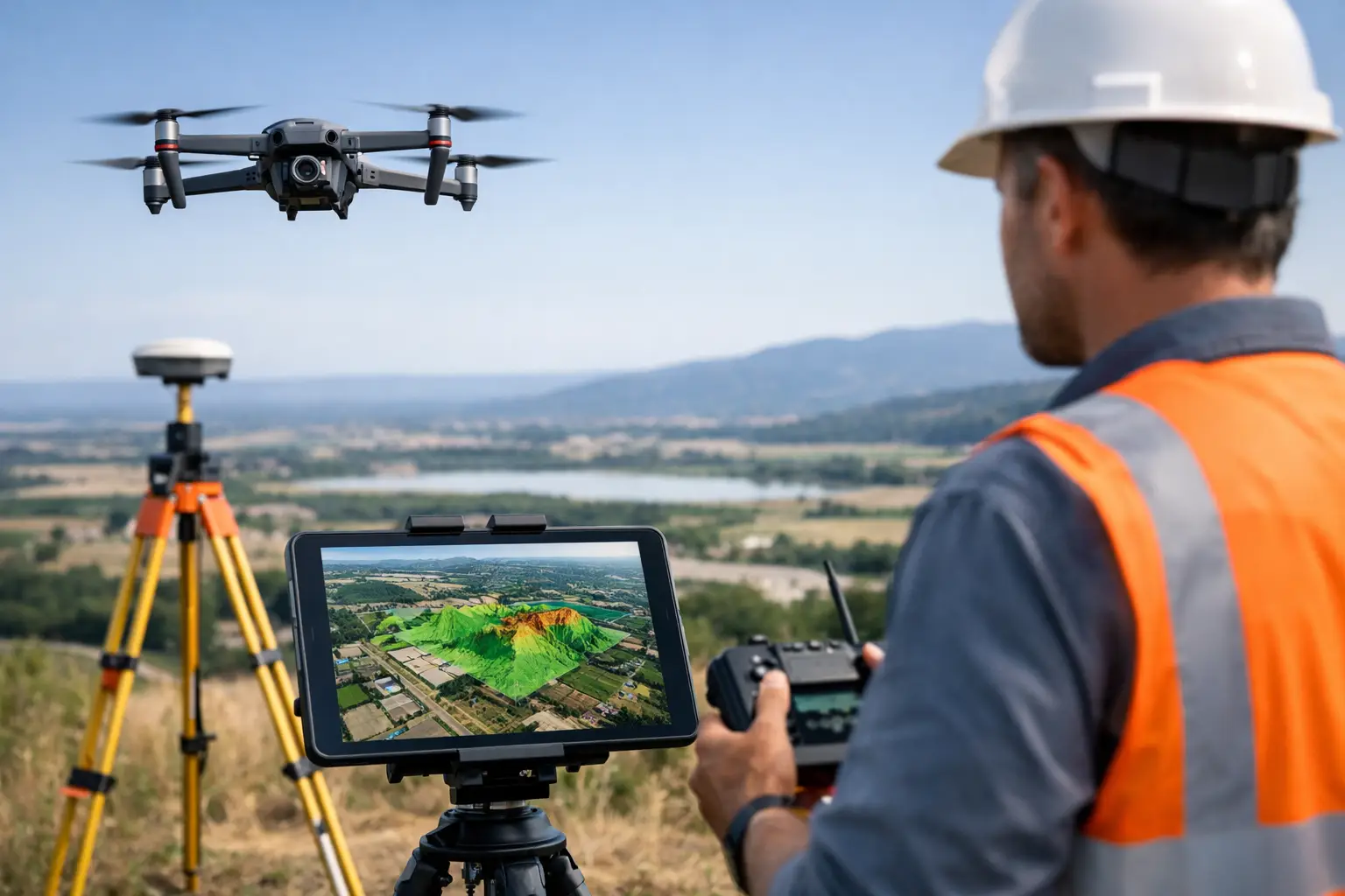
A construction site can change materially in a matter of days. Stockpiles move, excavation advances, access routes shift and temporary works appear. What is drone orthomosaic mapping in this context? It is the process of producing one geometrically corrected, measurable aerial image from many overlapping drone photographs, creating a reliable visual record of the site at a defined point in time.
Unlike a standard drone photograph, an orthomosaic is processed to remove the effects of camera angle, terrain variation and perspective. When captured and controlled correctly, it can be used within surveying, design, planning and asset-management workflows as a scaled map rather than simply an attractive aerial image.
What is drone orthomosaic mapping?
Drone orthomosaic mapping combines photogrammetry, accurate positioning and image processing. A drone flies a planned mission over an area, taking hundreds or thousands of overlapping images. Specialist software identifies common points between photographs, reconstructs the scene and stitches the imagery into a single seamless map.
The critical stage is orthorectification. Each image is adjusted using the camera model, flight position and elevation data so that features are represented in their correct ground position. The result is an orthomosaic: a top-down image in which distances, areas and coordinates can be measured.
This makes orthomosaic mapping valuable where teams need a current, intelligible overview of a site without walking every metre of it. It is commonly used for topographic survey support, earthworks monitoring, construction progress, quarry and landfill management, agricultural assessment, drainage planning and inspection of large or difficult-to-access areas.
How an orthomosaic is created
A professional workflow starts before the drone leaves the ground. The required deliverable, site conditions, survey control, airspace constraints and desired accuracy must be established first. A visual progress record may need a different flight plan and control method from a CAD-referenced survey or a volumetric calculation.
Flight planning and image capture
The drone follows a repeatable grid flight at a selected height, typically collecting nadir imagery with the camera facing directly down. Images need substantial forward and side overlap so the processing software can match the same ground detail across multiple photographs.
Flight height determines ground sampling distance, often called GSD. GSD describes how much ground each pixel represents. A lower flight produces finer detail, but it also increases the number of images, flight time and processing demand. The right balance depends on whether the priority is broad site coverage, feature identification or high-detail measurement.
Lighting, wind, vegetation movement and surface texture also affect capture quality. Water, uniform sand, reflective roofs and dense foliage can be difficult for photogrammetry because there may be too little stable visual detail for reliable image matching.
Positioning and survey control
The drone’s onboard GNSS position provides a useful starting point, but it is not always sufficient for a survey-grade outcome. RTK or PPK drone workflows improve the accuracy of image geotags by applying correction data to the aircraft position.
For projects requiring demonstrable positional accuracy, surveyors may also establish ground control points, or GCPs, across the site. These visible targets are measured using GNSS/RTK equipment and used to constrain the orthomosaic during processing. Independent checkpoints should then be used to verify the finished dataset rather than merely confirm the control used to create it.
RTK does not automatically remove the need for ground control. On a straightforward, open site with an appropriate coordinate reference system and clear verification requirements, it may reduce the quantity of control required. Complex terrain, demanding specifications, poor satellite conditions or contractual survey tolerances can still justify a more rigorous control network.
Photogrammetric processing
Processing software aligns the imagery, calculates camera positions and produces a dense point cloud, digital surface model and orthomosaic. The output can be exported in common geospatial formats for use in GIS, CAD, modelling and reporting workflows.
The processor must define the correct coordinate system and vertical datum. This is particularly important on UK projects, where data may need to align with the National Grid, site control or an established engineering coordinate system. A visually convincing map in the wrong coordinate reference system is not an effective survey deliverable.
Why raw aerial images are not enough
A single drone image is affected by perspective. Features nearer the edge of the image can appear displaced, and tall objects may lean away from the image centre. Measuring directly from that photograph can produce misleading results.
An orthomosaic corrects these distortions as far as the source imagery, terrain model and control allow. Roads, kerb lines, roof edges and ground features are placed in a common map view, enabling area and distance measurements. It also gives project teams one detailed reference image rather than a folder of disconnected photographs.
That distinction matters when data informs quantities, design decisions, payment assessments or compliance records. An orthomosaic can support these activities, but it should not be represented as a precise survey without appropriate control, verification and a clear understanding of its limitations.
Accuracy: what can be expected?
Orthomosaic accuracy depends on the entire workflow, not just the drone model. Camera quality, flight height, image overlap, RTK or PPK corrections, GCP distribution, terrain, processing settings and quality assurance all contribute to the final result.
For well-planned professional projects using suitable equipment and robust survey control, centimetre-level horizontal accuracy may be achievable. However, a claimed accuracy figure should always state how it was tested, which reference system was used and whether it refers to control-point residuals or independent checkpoint accuracy.
Vertical accuracy usually demands greater care than horizontal accuracy. Orthomosaics are primarily an image product, while levels and volumes are derived from the associated elevation model. Long grass, standing water, shadows and obstructions can reduce the reliability of the surface model. Where the requirement is to map bare earth beneath dense vegetation, drone LiDAR may be a more appropriate method than image-based photogrammetry.
Typical professional applications
On construction and civil engineering projects, regular orthomosaics provide a consistent visual record of progress. Teams can compare dates, identify changes, annotate issues and communicate site status to stakeholders without relying on ground photography alone. When combined with a surface model, the same capture can support cut-and-fill checks and stockpile volume calculations.
For utilities and infrastructure operators, an orthomosaic can provide an accessible base layer for corridor planning, asset context and inspection preparation. It does not replace close-up inspection where condition detail is required, but it can reduce time spent identifying access routes, locating features and planning safe field activity.
In agriculture and land management, high-resolution orthomosaics help document field boundaries, drainage features, crop variation and access conditions. RGB imagery has limitations for crop-health analysis, so multispectral sensors may be selected where the objective is vegetation indices rather than visual mapping.
Heritage, estates and planning teams can use orthomosaic outputs to document sites before and after works, map roof or ground conditions, and provide clear evidence for consultation or design discussions. The benefit is not merely coverage. It is the ability to relate imagery to known coordinates and other spatial datasets.
Choosing the right approach for the project
Drone orthomosaic mapping is most effective when the specification begins with the business decision the data must support. If the need is a clear, repeatable site record, a standard RGB survey with reliable georeferencing may be suitable. If the output must integrate with engineering design, establish earthworks quantities or meet specified tolerances, survey control, verification and experienced data processing become essential.
It is also worth considering whether photogrammetry is the right sensing method. Open ground, buildings, hardstanding and stockpiles are well suited to image-based mapping. Dense woodland, complex structures, featureless surfaces and areas where ground visibility is poor may require LiDAR, terrestrial scanning or a combined capture approach.
A complete deliverable should define more than the image file. It should state the coordinate system, GSD, capture date, control method, accuracy assessment, exclusions and supplied formats. This gives survey, engineering and commercial teams confidence that the dataset is fit for its intended use.
For organisations building an in-house workflow, the practical choice is not simply which drone to purchase. It is how aircraft, RTK corrections, ground control, processing software, operator competence and quality assurance will work together. LiDAR Tech UK can help define that workflow around the required accuracy, site conditions and final data outputs, whether the requirement is equipment supply, training or a delivered mapping service.
The strongest orthomosaic is one that answers a specific site question with evidence the wider project team can trust.