
A LiDAR scan can capture millions of points in minutes, but it cannot compensate for control that is poorly planned, inconsistently observed or referenced to the wrong coordinate system. Survey control with GNSS provides the geographic framework that gives site data a dependable position, orientation and scale – whether the final deliverable is a topographic survey, volume calculation, setting-out model, point cloud or orthomosaic.
For UK survey and construction teams, the value is not simply faster coordinate collection. A properly designed GNSS control network reduces repeat visits, supports consistent work between contractors and gives downstream CAD, BIM and asset-management data a defensible spatial reference.
What survey control with GNSS achieves
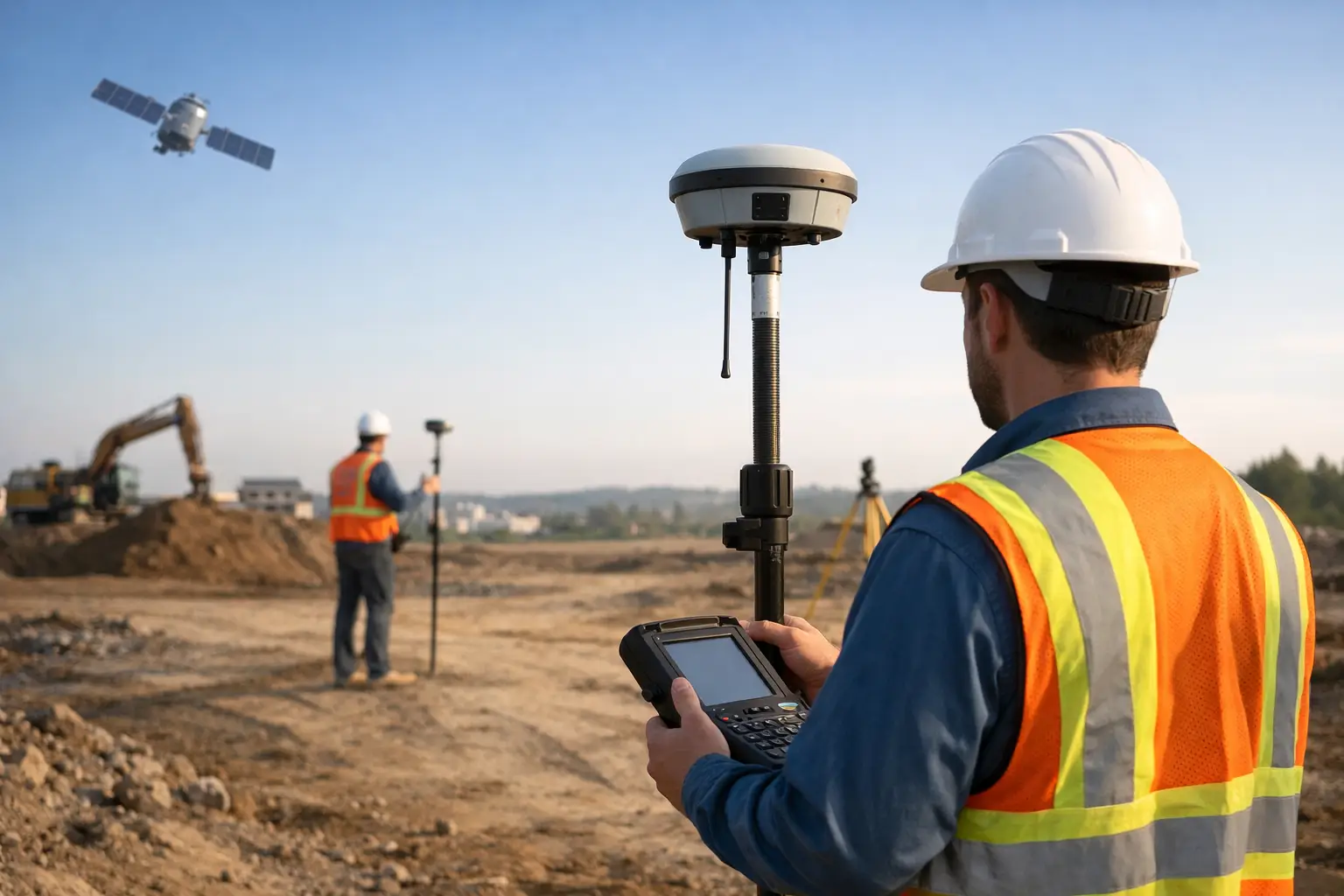
Survey control is the network of known points used to position survey observations and construction activity. These points may establish horizontal coordinates, height, or both. With GNSS, a rover receives satellite signals and correction data to calculate its position relative to a reference station or correction network.
In an RTK workflow, the receiver can deliver centimetre-level positions in real time when conditions are suitable. That makes it highly effective for establishing control on open sites, checking existing coordinates, collecting ground features and setting out design positions. A base-and-rover arrangement is often appropriate where a project requires independent local control, while a network RTK service can improve mobilisation where coverage and communications are reliable.
The practical outcome is a common reference for every survey method used on the project. GNSS control can tie together total-station observations, terrestrial LiDAR, mobile mapping, drone photogrammetry and machine-control data. Without that reference, datasets may look accurate in isolation while failing to align when overlaid in design or GIS software.
Start with the required accuracy, not the equipment
GNSS is capable of high accuracy, but the specification must reflect the job. A boundary-related survey, structural setting out and a reconnaissance survey do not carry the same tolerance. The required confidence level should be agreed before fieldwork begins, along with the coordinate reference system, vertical datum, deliverable format and checking procedure.
For many UK projects, coordinates need to be compatible with the National Grid and Ordnance Datum Newlyn, typically through an appropriate transformation and geoid model. This is where a casual approach can create costly discrepancies. GNSS ellipsoidal heights are not the same as project levels, and a dataset can be horizontally correct while carrying an unacceptable vertical offset.
A control strategy should answer straightforward questions early: Is the client working on national coordinates or a local engineering grid? Are published control marks available and suitable? What positional tolerance applies to the final asset or model? Will the control be used only for a one-day survey, or retained for phased construction and future monitoring?
The answers determine whether a network RTK rover is sufficient, whether static GNSS observations are required, and where total-station control should supplement satellite positioning.
Establishing a dependable GNSS control network
Control points need locations that are stable, accessible and fit for purpose. A point placed in loose ground, beside a haul road or where it will be buried by temporary works is unlikely to serve a long programme. On construction sites, points should also be protected from plant movements and clearly documented so other teams can identify them.
Good satellite visibility remains essential. Trees, high-rise structures, cranes, cuttings and reflective surfaces can obstruct signals or cause multipath, where reflected signals distort the position solution. A receiver may show a fixed RTK solution in challenging conditions, but that alone is not proof that the result meets the survey tolerance.
Field teams should allow sufficient observation time for the task, use an accurately measured antenna height and record the equipment, correction source, coordinate system and quality indicators. Reoccupying points at different times of day can help expose poor geometry or local interference. For higher-consequence work, independent checks from a separate occupation, base setup or total station provide stronger evidence than repeated measurements made under the same conditions.
Control should not rely on a single point. A site needs enough well-distributed points to support the intended work and identify errors. The right number depends on site size, terrain, visibility and tolerances, but a small cluster at one edge of a project offers limited resilience for a large earthworks, highway or utilities scheme.
Check positions independently
The most valuable control observation is often the independent check. After establishing a point, occupy another known point or compare against a verified total-station observation. Record residuals and assess them against the project specification rather than accepting a result because it appears plausible.
This discipline is particularly important when bringing historic drawings, legacy control or third-party coordinates onto a live site. Datum assumptions, transcription errors and incorrect grid-to-ground factors can all create offsets that only become obvious once work is underway.
Where GNSS control performs well – and where it does not
GNSS performs particularly well on open ground, linear infrastructure routes, earthworks, agricultural land, quarries and large development sites. It enables rapid control extension without the line-of-sight requirements of a total station, making it a practical tool for early-stage surveys and frequent progress checks.
It is less suitable as the sole control method beneath dense canopy, close to tall façades, inside buildings, under bridges or in narrow urban corridors. These are not equipment failures; they are environmental limits of satellite-based positioning. In such areas, GNSS may establish primary control in open locations, while a total station transfers that control into obstructed zones.
The same principle applies to height-critical work. RTK-derived levels are highly useful, but the required method depends on tolerance, local conditions and the project specification. For precise structural works or verification against established benchmarks, conventional levelling may remain the right control method. The strongest workflows use each instrument where it has the greatest technical advantage.
Connecting GNSS control to LiDAR and drone surveys
LiDAR and drone projects benefit directly from well-managed control because positional confidence must carry through to the final model. Terrestrial LiDAR scans require survey control or target measurements to register scan positions accurately within the project coordinate system. Mobile or SLAM-based systems can collect data quickly, but control points and check points remain essential where an absolute coordinate accuracy is required.
For drone photogrammetry, GNSS control supports ground control points and independent checkpoints. Even when an enterprise drone uses RTK positioning, control still has a role. RTK improves image geotagging and operational efficiency, but independently surveyed checkpoints are the practical way to verify the accuracy of the processed orthomosaic or surface model.
The distinction matters commercially. A visually impressive point cloud or model is not automatically survey-grade. The deliverable should state its coordinate reference system, control methodology, achieved check-point residuals and any limitations caused by access, vegetation, flight conditions or satellite visibility.
A field workflow that protects data quality
A consistent process prevents most avoidable GNSS control errors. Before attending site, confirm the coordinate reference system, correction service availability, site access constraints and expected obstructions. Review whether existing marks are reliable rather than assuming that a labelled bolt or stake is valid control.
On site, establish or verify primary points in clear locations, then measure secondary control as needed for scanning, setting out or drone targets. Keep a concise control register with point names, coordinates, descriptions, photographs, observation details and check results. This record is often as valuable as the coordinate file when questions arise months later.
Before demobilising, inspect the data for duplicated point IDs, implausible heights, incorrect rod or antenna settings, and coordinate-system errors. A short independent check while equipment is still on site is considerably cheaper than remobilising after drawings or models have been issued.
Choosing a GNSS solution for operational work
Professional GNSS equipment should be selected around the workflow, not just the headline accuracy figure. Consider multi-constellation and multi-frequency tracking, tilt compensation requirements, correction-service compatibility, cellular connectivity, battery endurance, controller software, data export and integration with existing CAD or survey software.
Support is equally relevant. A new rover is only productive when teams understand datum configuration, field coding, quality controls and how to diagnose a poor fix. LiDAR Tech UK supports GNSS, RTK, LiDAR and drone workflows as connected systems, helping organisations match equipment and field procedures to the accuracy their projects demand.
Survey control is the quiet part of a project that determines whether every later measurement can be trusted. Specify it carefully, observe it independently and preserve the record. Those decisions give the site team reliable coordinates today and usable spatial data long after the works have moved on.