
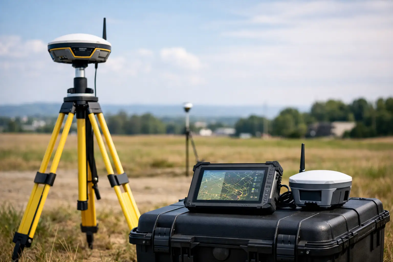
A GNSS base is only as reliable as the control behind it. A high-specification rover can still produce poor positions if the base has been placed beneath obstructions, assigned the wrong coordinate system or configured with an incorrect antenna height. Knowing how to set up GNSS base equipment correctly is therefore fundamental to producing repeatable RTK results for setting out, topographic surveys, machine control and asset capture.
For UK projects, the objective is not simply to achieve a fixed solution. It is to achieve a fixed solution that agrees with the required site grid, datum and level reference, and that can be verified throughout the working day.
Start with the required survey control
Before erecting the tripod, establish what the delivered data must match. This is particularly important where a project combines GNSS observations with total station work, existing design models, OS mapping or client-issued control.
Confirm the horizontal datum and coordinate system, the vertical datum and geoid model, and whether the project uses a local site calibration. A base broadcasting ETRS89 positions while the rover is expected to deliver OSGB36 National Grid coordinates will introduce a consistent but potentially significant discrepancy. Likewise, ellipsoidal heights are not interchangeable with orthometric levels used for construction and drainage work.
If verified control marks are available, occupy one of them. This provides the strongest basis for a local RTK setup because the base coordinate is known rather than estimated. Use the published coordinate values exactly as supplied, including the correct unit and coordinate order. Check whether heights refer to the ground mark, a reference point or an antenna reference point.
Where no established control exists, an averaged autonomous position can support lower-risk work such as rapid mapping, volume estimates or initial site reconnaissance. It should not be treated as permanent survey control. The resulting coordinates may shift between sessions and will not necessarily agree with other survey datasets.
Choose a base location that protects signal quality
The best base location is stable, open to the sky and representative of the working area. A permanent survey pillar, a sound control point or a securely planted tripod on firm ground is preferable to a pavement edge, temporary compound surface or anything likely to move during the survey.
Keep the antenna clear of trees, cranes, buildings, metal cladding and parked plant. These features obstruct satellite signals and can cause multipath, where reflected signals reach the antenna after the direct signal. Multipath can reduce repeatability even when the receiver reports an RTK fixed status.
A clear horizon is valuable, but practical site conditions often require compromise. If the only viable point has partial obstruction, identify the affected directions and test the rover at the extremities of the intended survey area. A base on high ground may provide better radio coverage, but only if it remains secure and does not force unsafe access or expose equipment to site traffic.
For longer occupations, protect the setup from accidental disturbance. Use a sturdy tripod, fully seat its feet and mark the position if the base needs to be re-established later. On active construction sites, barriers and clear communication with site management are often as important as receiver settings.
How to set up GNSS base hardware accurately
Mount the GNSS antenna or integrated receiver on a tribrach and tripod, then centre it precisely over the control mark. Use the optical plummet where available and level the tribrach before entering any coordinates. Integrated receiver systems with tilt compensation can make field work faster, but the base itself should still be level and centred unless the manufacturer specifically supports an alternative method.
Measure the antenna height carefully. This is one of the most common sources of avoidable error. Receiver software may ask for a slant height, vertical height or a measurement to a specific antenna reference point. Select the measurement method that matches the equipment and record it in the survey notes.
Do not assume a tape measurement is correct because it was taken once. Measure the height twice from different directions and compare the values. If the readings disagree, resolve the reason before starting the broadcast. A few millimetres of error at the base can directly affect rover elevations across the site.
Enter the known base coordinates, select the correct datum, projection and geoid, and allow the receiver to initialise fully. If operating on a local grid, load the approved localisation or calibration file rather than attempting to recreate parameters from memory. A properly documented configuration is essential where multiple crews or return visits are involved.
Configure the correction link
The base must send corrections to the rover through either a UHF radio link or an internet-based NTRIP connection. The right method depends on site geography, communication infrastructure, required range and project operating model.
UHF is often effective on contained sites where mobile coverage is poor or corrections must remain independent of an external network. Set the same radio protocol, frequency, channel spacing and data rate on both base and rover. Radio power should be appropriate to the required coverage, not automatically set to maximum. Higher output can improve range, but it consumes more power and must comply with applicable UK radio licensing and frequency requirements.
An NTRIP setup can be useful where a stable internet connection is available and teams need corrections across dispersed locations. The base requires a reliable mobile data connection and an NTRIP caster or correction service configuration. Confirm that the mountpoint, format and credentials are correctly entered, then verify that correction age remains low at the rover.
In either case, match the correction message format to the rover capability. RTCM is the common choice for modern multi-constellation systems, but the selected version and enabled constellations must be compatible across the workflow. GPS, Galileo, GLONASS and BeiDou observations can improve availability in challenging environments, provided both units are configured consistently.
Initialise the rover and check the result
At the rover, connect to the base correction stream and wait for an RTK fixed solution. Check more than the word “fixed”. Review correction age, satellite count, PDOP, radio signal or internet stability, and reported horizontal and vertical precision. A fixed solution with high correction age or intermittent communications should be investigated before work starts.
The first practical quality-control test is to measure a second known point. Occupy it for long enough to obtain stable readings, then compare the observed position and level against the published values. Repeat the observation after moving away and returning to the point. This confirms that the base coordinate, antenna height, localisation and correction link are all working together.
For engineering work, establish project tolerances before deciding what constitutes an acceptable check. A general topographic survey may permit a different tolerance from kerb setting out, structural works or as-built verification. Record the observed residuals, time, receiver details and correction method so results remain defensible if queried later.
Maintain control throughout the day
A satisfactory start-up check does not remove the need for ongoing verification. Re-check a known point after breaks, after moving the base, following a power interruption, and before issuing final data. If the check changes unexpectedly, stop collecting critical observations until the source has been identified.
Common causes include a disturbed tripod, an incorrect antenna-height entry after restarting the controller, a changed coordinate system, radio interference or a rover that has reverted from fixed to float. Tree canopy and changing satellite geometry can also affect field performance, particularly in urban corridors, woodland and steep-sided sites.
Keep concise field records: base point ID, coordinate source, antenna height and measurement method, radio or NTRIP settings, start and finish times, and check-point results. These notes allow a survey team to reproduce the setup, support QA procedures and quickly isolate issues when data does not align.
For teams deploying RTK systems across varied UK sites, LiDAR Tech UK can assist with receiver configuration, site workflows and training aligned to the required survey output. The most productive setup is the one that is not only fast to deploy, but also straightforward to validate and repeat.
A GNSS base should be treated as the control centre of the survey, not merely a transmitter on a tripod. Give the coordinate reference, antenna height and independent checks the same attention as the rover measurement, and your RTK data will carry the consistency needed for confident decisions on site.