
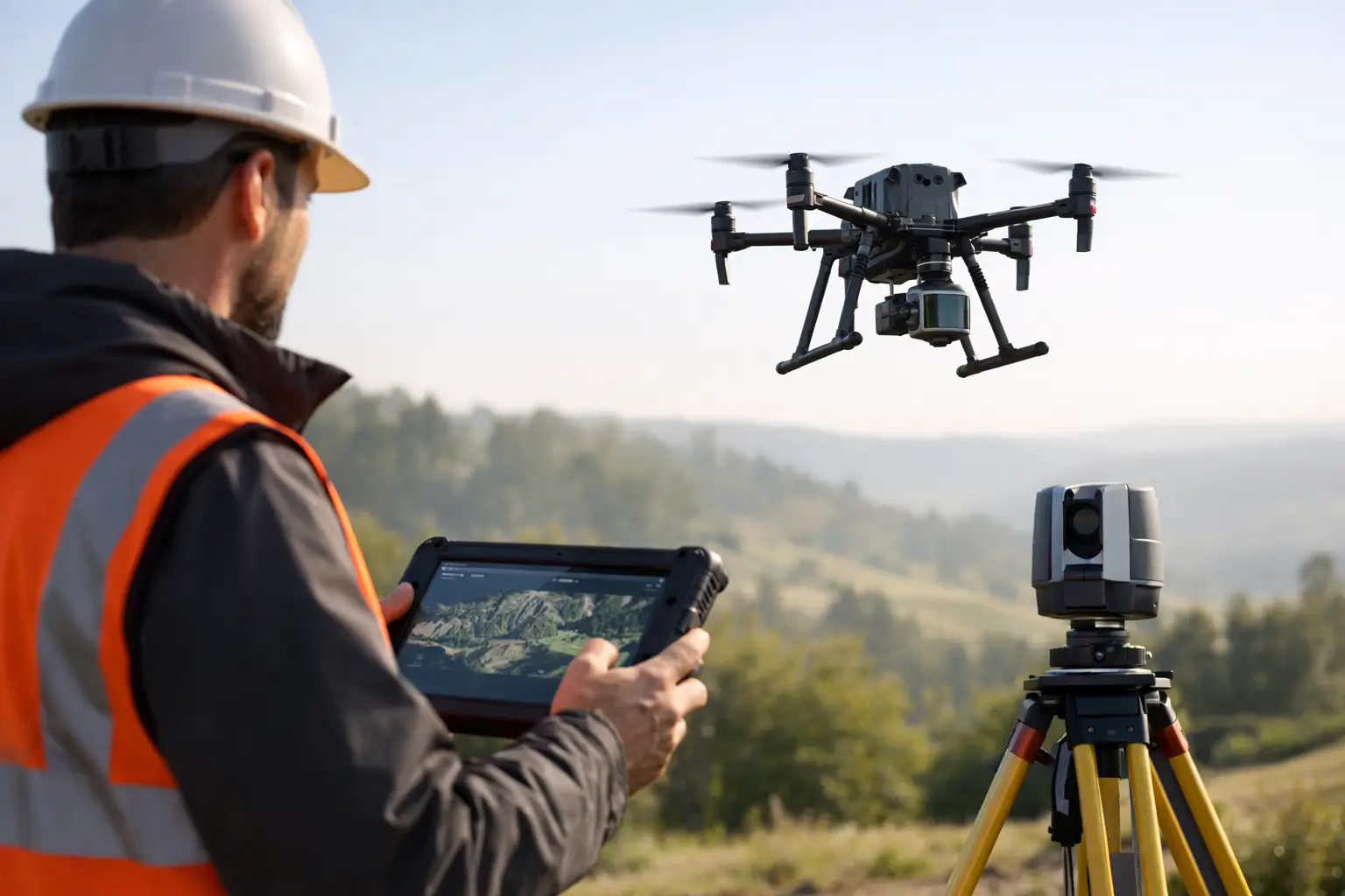
A point cloud is only as valuable as the decisions made before the scanner is switched on. This guide to LiDAR data capture is intended for UK survey, construction and asset teams that need reliable, usable spatial data rather than a large file that creates more work in the office. The objective is to define the required output, select a capture method that suits the site, establish dependable control and maintain quality checks from fieldwork through to delivery.
Start with the required deliverable
LiDAR capture should begin with the question: what will the data be used for? A topographic survey, volume calculation, BIM model, highway corridor, asset inventory and heritage record each require a different balance of accuracy, density, coverage and classification.
For example, a contractor checking cut and fill may need a georeferenced surface model delivered quickly. An engineering team producing a detailed design model may require more stringent control, defined feature extraction and CAD-ready linework. A facilities manager documenting plant rooms may prioritise complete coverage around equipment and clear imagery to support identification.
Set the specification before mobilisation. It should identify the coordinate reference system, vertical datum, required accuracy, point density, deliverable formats, exclusions and tolerances. Agree whether the client needs raw point clouds, registered scans, classified data, a digital terrain model, orthomosaic, mesh, 3D model or drawing output. This avoids a common failure point: capturing a technically impressive dataset that is unsuitable for the intended workflow.
Guide to LiDAR data capture: choose the right platform
There is no single best LiDAR platform. The correct choice depends on the environment, access constraints, level of detail and acceptable survey duration.
Mobile and handheld LiDAR
Handheld and mobile LiDAR systems are effective for buildings, stockpiles, industrial facilities, streetscapes and complex sites where the operator can walk the required route. SLAM-based scanners can collect extensive data rapidly, including areas that are slow to cover with static scanning. They are particularly useful where access is intermittent or where teams need to capture progress information without disrupting site activity.
The trade-off is that SLAM accuracy depends on the quality of the trajectory and the geometry of the environment. Long, featureless corridors, repetitive warehouse racking and open areas with few fixed features can increase drift risk. Closing loops, maintaining consistent walking speed, scanning from multiple directions and using surveyed control points will improve confidence in the final dataset.
Static terrestrial laser scanning
Static terrestrial scanners remain the preferred option where maximum local detail, repeatable accuracy and comprehensive line-of-sight coverage are required. They suit structural surveys, heritage documentation, plant rooms, façades and legal or engineering work where every critical feature must be defensible.
This method takes longer in the field because each scanner position requires set-up and registration planning. However, it can be the right commercial choice when a missed detail or poorly controlled model would cause design delay, rework or access costs later in the project.
UAV LiDAR
Drone-based LiDAR is suited to larger sites, inaccessible terrain, transport corridors, quarries, forestry and utilities routes. It can capture terrain through light to moderate vegetation more effectively than image-based photogrammetry, depending on canopy density and the required ground return. It also reduces exposure to steep slopes, unstable ground and live operational areas.
UAV LiDAR requires careful flight planning, appropriate permissions, site risk assessment and a realistic view of weather conditions. Wind, rain, low light for supporting imagery, battery management and airspace restrictions all affect productivity. The flight plan should provide sufficient overlap and a consistent height above ground, while the sensor configuration must match the target point density and vegetation conditions.
Vehicle-mounted and hybrid workflows
For roads, rail-adjacent assets and long linear networks, vehicle-mounted systems can collect data at a pace that walking or static scans cannot match. In many projects, a hybrid approach is more effective: UAV LiDAR for broad coverage, mobile scanning for ground-level detail, and static scans for critical structures or concealed areas.
The benefit is not simply faster capture. Combining methods closes line-of-sight gaps and gives designers a more complete representation of the site. The drawback is added registration and processing discipline, so the control strategy must be shared across every platform.
Establish survey control before collecting data
Survey control is the backbone of professional LiDAR work. If control is weak, even a dense and visually convincing point cloud can be displaced, tilted or inconsistent with existing design data.
Use established control where it is verified and suitable for the required accuracy. Where new control is needed, GNSS/RTK methods can provide efficient site coverage, while total station observations may be necessary where satellite visibility is limited or tighter local precision is required. Check the coordinate system and transformation parameters against the client’s project requirements rather than assuming a site grid or legacy drawing is correct.
Ground control points and check points serve different purposes. Control points are used to constrain or georeference the dataset. Independent check points test the final result. Keep them separate where possible. A dataset that fits its own control points well has not necessarily demonstrated independent accuracy.
For mobile LiDAR, establish visible, well-distributed targets where the workflow benefits from them. For UAV work, position control across the full site extent and consider height variation, not just plan position. Avoid placing all points along one boundary or in easy-to-access areas. Control needs to test the terrain and geometry that matter to the final deliverable.
Plan the route, scan geometry and site access
A reliable capture plan considers how the sensor will see every required surface. Walk the site before scanning where practical. Identify reflective materials, glass, water, narrow spaces, moving machinery, overhead obstructions, vegetation and areas where staff or public movement could affect the survey.
For handheld LiDAR, plan a route with deliberate loop closures. Return to previously scanned areas, revisit key junctions and avoid making one long outward journey with no opportunity for the system to reconcile its position. In buildings, scan rooms in a sequence that creates strong overlap through doorways and corridors.
For UAV LiDAR, define flight lines around terrain, obstructions and desired ground density. Consider whether cross-flight lines are needed to strengthen the trajectory solution or improve coverage on slopes. Maintain safe separation from people, structures and operational activity, and plan take-off and landing locations that do not compromise the survey or site safety.
Do not treat site access as an administrative detail. A scan may need possession arrangements, permits, a banksman, traffic management, induction clearance or escort access. These constraints influence both platform choice and programme. Planning them early prevents rushed field decisions that reduce data quality.
Capture with quality assurance built into the fieldwork
Field checks are faster and cheaper than revisiting a site. Review coverage during collection rather than waiting until processing is complete. Confirm that critical surfaces are visible, control targets are captured clearly, and the scan route or flight path has not been interrupted by a battery issue, GNSS outage or unexpected restriction.
Monitor positioning status throughout the survey. RTK corrections, satellite geometry, multipath, obstructions and loss of communications can affect georeferencing. If a correction service is unavailable or conditions deteriorate, record the issue and decide whether the work can continue under an alternative control method. Do not rely on a later software adjustment to resolve an unrecorded positioning problem.
Keep clear field records. Note scanner settings, scan identifiers, control observations, weather, access limitations and any areas that could not be collected. These records support processing decisions and provide an audit trail when a client asks how an accuracy result was achieved.
Process for the intended use, not just visual appeal
Processing should preserve traceability from raw capture to deliverable. Register scans, apply control, inspect residuals and compare independent check points before exporting final data. Review the point cloud in sections as well as in 3D. Misalignments, duplicated surfaces and trajectory drift can be difficult to spot in a visually attractive overview.
Classification and filtering need careful judgement. Ground filtering in vegetated terrain can remove valid terrain points or retain low vegetation. Noise reduction can improve readability but may also remove small features that matter to an asset survey. Agree the level of cleaning required and retain an archived source dataset where project requirements permit.
Deliver data in formats that fit the client’s software and downstream tasks. This may include LAS or LAZ point clouds, E57 exchange files, RCP or RCS project formats, CAD drawings, terrain models, meshes or tabulated asset information. Include a concise report covering the capture method, coordinate system, control, checks completed, accuracy results and known limitations.
When accuracy claims need context
Quoted scanner accuracy is only one part of the final accuracy budget. Range, incidence angle, surface material, control quality, registration method, operator technique and processing settings can all influence the result. A manufacturer specification should therefore be treated as a component performance figure, not an automatic project outcome.
For commercially sensitive work, define acceptance criteria in measurable terms. State whether accuracy is assessed against check points, surfaces, identifiable features or model elements. Specify the confidence level where appropriate and make clear which areas are outside scope. This protects both the survey team and the end user from assumptions that point-cloud density alone equals survey certainty.
LiDAR Tech UK supports organisations that need to select, deploy and process professional LiDAR workflows, from equipment and positioning solutions through to survey deliverables. The most effective next step is to review a representative site, required outputs and accuracy tolerance before committing to a platform. That conversation usually reveals whether the priority is speed, detail, access, repeatability or a practical combination of all five.