
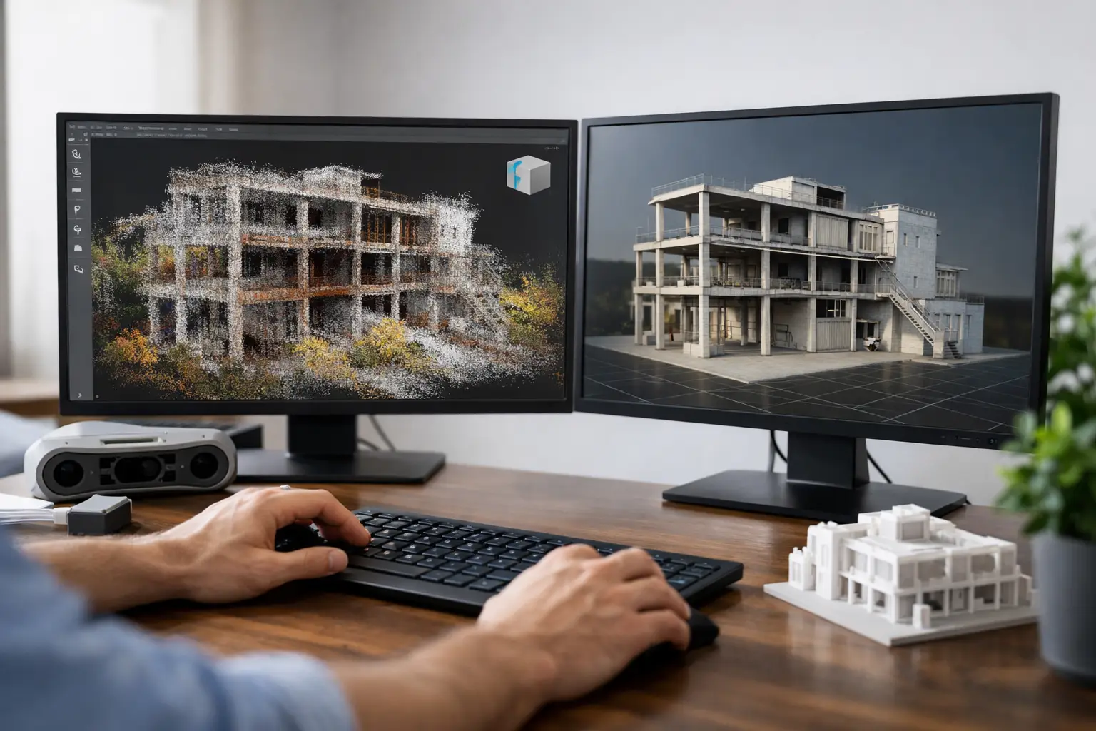
A point cloud can record millions of measured positions in a matter of minutes, but it is not automatically a usable model. The value comes from converting that measurement-rich dataset into geometry that a design team, asset manager or contractor can interrogate with confidence. This guide to 3D modelling from point clouds sets out the workflow, decisions and quality controls that determine whether the final model is fit for purpose.
Start with the required model, not the scan
The most costly point-cloud modelling problems usually begin before the scanner is switched on. A detailed scan cannot compensate for an undefined deliverable. Before capture, establish what the model must support: measured surveys, clash coordination, refurbishment design, heritage recording, quantity planning, asset management or visualisation.
That intended use sets the required level of detail, accuracy, coordinate reference and model format. A model for early-stage space planning may only need primary walls, floors, ceilings and structural openings. A fabrication or plant-room coordination model may require pipework, valves, cable containment, supports and equipment connections. Trying to model every visible item on every project adds cost, extends programme time and can make the file difficult to use.
Agree the following at the outset: the survey control and coordinate system, required positional tolerance, modelled elements, exclusions, file formats, naming convention and the software environment in which the client will use the data. For UK construction work, this often includes a clear decision on whether the deliverable is a georeferenced survey model, a Revit model, CAD drawings, a mesh, or a combination of these outputs.
Capture a point cloud that supports modelling
A successful model begins with complete, well-registered data. Terrestrial LiDAR is generally the preferred choice for interiors, complex structures and plant areas because it captures dense geometry with controlled coverage. Mobile mapping can improve productivity across larger sites, while drone LiDAR or photogrammetry can capture roofs, facades, terrain and inaccessible external assets.
Each approach has trade-offs. Static scanning offers high detail and dependable coverage but requires more station planning. Mobile scanning is faster, particularly along corridors or through large buildings, but depends on a disciplined walking route, suitable SLAM conditions and appropriate control. Drone capture reduces working-at-height exposure and provides valuable roof data, although vegetation, reflective surfaces and line-of-sight constraints still affect results.
Plan scan positions around occlusions rather than simply working to a regular grid. Dense plant, suspended ceilings, racking, parked vehicles and open doorways can all hide important geometry. Where possible, capture overlapping views from different elevations and directions. Include survey control where project accuracy, repeatability or integration with existing design data demands it.
Field checks are more efficient than return visits. Review coverage on site, confirm that key interfaces are visible, and identify whether surfaces such as glass, polished metal or dark finishes have produced poor returns. These materials can create holes, noise or false points, so important dimensions may need supplementary total-station observations or manual measurement.
Registration and georeferencing
Registration combines individual scans into one coordinated point cloud. The process may use cloud-to-cloud alignment, targets, surveyed control or a combination of methods. Registration reports are useful, but a low reported error alone does not prove a correct result. Repetitive spaces, long corridors and similar structural bays can permit a visually plausible but incorrect alignment.
Check registration against independent control and inspect known features across scan boundaries. If the model must align with a site grid, engineering design or GIS dataset, establish that reference early. Retrofitting coordinates after modelling creates avoidable rework and can introduce uncertainty into every downstream drawing and schedule.
Process the cloud without removing useful evidence
Raw point clouds contain more than the permanent built environment. People, vehicles, temporary materials, rain, moving machinery and scanning artefacts all need consideration. Processing should remove irrelevant noise while retaining evidence needed for interpretation.
The usual preparation sequence is registration, georeferencing, clipping, classification where appropriate, decimation for viewing, and export into the modelling environment. Maintain a secure copy of the original registered dataset. The source cloud is the survey record, while a cleaned working cloud is an efficient modelling reference.
Decimation needs care. Reducing point density can make large datasets manageable in CAD or BIM software, but aggressive thinning may remove detail at corners, pipe runs, ornate features or thin structural members. It is often better to use a lighter cloud for general navigation and retain high-density clipped regions for detailed modelling.
Colour imagery can assist interpretation, particularly where geometry alone cannot distinguish materials, services or labels. It should not, however, be treated as proof of concealed construction. A point cloud records visible surfaces. It does not show what is behind a wall, inside a duct, beneath insulation or below ground unless those elements were exposed and captured.
Choose the right modelling method
There is no single correct way to convert a point cloud into a 3D model. The appropriate method depends on the asset, required detail and expected use.
For buildings and infrastructure, feature-based or parametric modelling is normally the most useful route. Operators trace and construct walls, slabs, beams, openings, MEP services and equipment as intelligent CAD or BIM objects. This produces a model that can support drawings, coordination, schedules and design development, but it requires interpretation. Existing buildings are rarely perfectly square, level or consistent, so forcing irregular surveyed geometry into idealised objects can conceal valuable information.
Mesh modelling converts the visible cloud surface into connected triangles. It is effective for complex forms, heritage features, rock faces, facades and as-built visualisation. Meshes represent shape well but are less suited to editable construction objects, reliable schedules or design coordination. File sizes can also become substantial.
Surface and solid modelling sits between these approaches. It can be suitable for industrial plant, tunnels, fabricated components and terrain where accurate geometry matters more than BIM intelligence. In practice, many projects benefit from a hybrid output: a clean mesh for complex geometry, supported by parametric objects for key building and asset elements.
Model to the evidence, not to assumptions
Modelled geometry should follow the point cloud within the agreed tolerance, while recognising the limitations of capture. Edges may be blurred by scan resolution, objects may be partially obscured, and soft or reflective surfaces can be unreliable. Where a feature is inferred rather than directly observed, record that limitation clearly.
Avoid making walls artificially straight or pipework artificially circular simply because the authoring software prefers standard objects. For refurbishment and retrofit work, the deviation from nominal geometry is often precisely what the design team needs to understand. Equally, modelling every minor defect in an old wall may not improve a design model. The agreed specification should determine the balance between measured fidelity and usable geometry.
Quality assurance for a dependable model
Quality assurance should run throughout the workflow rather than being left to a final visual check. Compare model objects back to the point cloud from multiple viewpoints and use sections to inspect alignment at junctions, openings and service routes. Check dimensions against control measurements and focus attention on areas where design risk is highest.
A practical QA review should confirm four things:
- The model is correctly positioned, orientated and scaled within the agreed coordinate system.
- Geometry follows the source data within the specified tolerance.
- Required elements are present, consistently classified and named.
- Exclusions, occluded areas and assumptions are documented for the receiving team.
The tolerance must reflect both the capture method and the purpose of the deliverable. A model for general estate planning and a model used to prefabricate services cannot be validated against the same standard. Clear acceptance criteria protect the client and supplier by ensuring that accuracy claims are relevant to the project rather than presented as a generic headline figure.
Deliver data people can use
A technically accurate model can still fail commercially if it is difficult to open, too heavy to navigate or incompatible with the project workflow. Confirm software versions and exchange formats before production begins. Native BIM files may be required for authoring teams, while IFC can support broader coordination. DWG, DXF, OBJ, E57, LAS or RCP files may also be needed depending on whether the recipient requires drawings, geometry or the underlying survey record.
Delivering the point cloud alongside the model gives designers a means of checking interpretation and reviewing areas that were intentionally excluded from modelling. A concise survey report should state the capture dates, equipment approach, control method, registration results, coordinate reference, model tolerance and known limitations. That information gives the model a defensible provenance when it is used months or years after the survey.
File management matters on live projects. Use disciplined naming, issue status and revision control so that teams do not coordinate against an obsolete scan or superseded model. For large estates or infrastructure programmes, consider dividing data by building, zone, floor or asset group to maintain practical file sizes without losing spatial context.
When specialist support adds value
Point-cloud modelling combines survey control, scanning practice, processing expertise and an understanding of CAD or BIM deliverables. Organisations that scan occasionally may find that training and a repeatable internal workflow provide the best return. Those facing a time-critical refurbishment, high-risk plant area or one-off heritage survey may be better served by an outsourced capture-to-model service.
LiDAR Tech UK supports both routes, supplying professional scanning systems alongside training, technical guidance and survey deliverables. The right choice depends on scan frequency, internal capability, required turnaround and the consequence of inaccurate data.
The most useful next step is not to request a model at a vague level of detail. Define the design decision, inspection task or asset-management outcome it must support, then specify the evidence and tolerance required to support it. That gives the survey and modelling team a clear target, and gives every downstream user data they can rely on.