Author: GaryH

  • When Should Surveyors Use LiDAR?

    When Should Surveyors Use LiDAR?

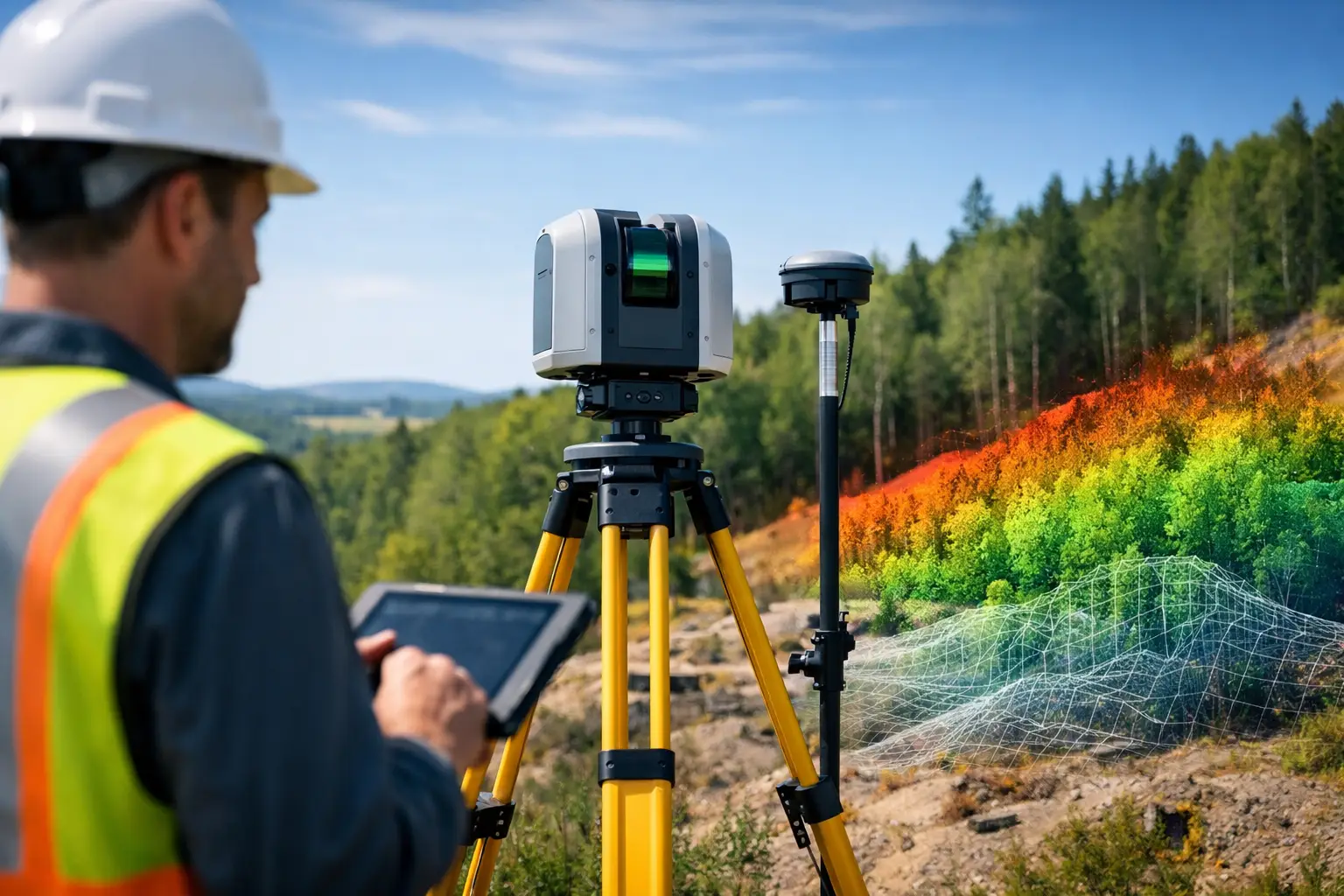
    A site with broken ground, dense vegetation and restricted access will expose the limits of conventional methods very quickly. That is usually the point where the question shifts from whether LiDAR is useful to when should surveyors use LiDAR as the primary capture method. For many professional teams, the answer comes down to speed, safety, surface complexity and the level of detail the client actually needs.

    LiDAR is not a universal replacement for total stations, GNSS or photogrammetry. It is a high-value tool when project conditions reward rapid 3D capture, repeatable coverage and reduced time on site. Used in the right setting, it can shorten field programmes, improve site safety and deliver denser datasets for design, measurement and asset records.

    When should surveyors use LiDAR on a project?

    Surveyors should use LiDAR when conventional workflows become too slow, too risky or too limited for the job in hand. That commonly includes topographic surveys over large or uneven ground, corridor mapping, stockpile measurement, façade and building documentation, vegetation-covered terrain, and asset inspection where physical access is poor.

    The core advantage is data density. Instead of recording selected points, LiDAR captures a detailed point cloud across the site or structure. That changes what the survey team can deliver afterwards. Measurements that were not specified on day one can often still be extracted later, which reduces return visits and gives design teams more complete context.

    Just as important is speed. Mobile, handheld, terrestrial and drone-based LiDAR systems can cover substantial areas in less time than traditional point-by-point methods. On active construction sites, rail environments, highways and utility corridors, less time in the field often means lower operational disruption and lower exposure to hazards.

    The clearest use cases for LiDAR

    Large areas where speed matters

    If the brief involves extensive coverage and a compressed programme, LiDAR is often the stronger option. Walking a site with a scanner or flying a LiDAR-equipped drone can capture terrain and features far faster than relying purely on manual observation and discrete measurements.

    This matters for land development, route planning and pre-construction surveys. When teams need accurate ground models quickly to support design decisions, LiDAR can improve both productivity and turnaround. The commercial value is straightforward – more area captured per day, with fewer gaps in the dataset.

    Complex surfaces and irregular geometry

    Retaining walls, embankments, bridge elements, pipework, plant rooms and heritage structures are difficult to represent properly with sparse point collection. LiDAR performs well where shape matters. The denser the geometry, the more value there is in collecting a continuous 3D record rather than isolated shots.

    For measured building surveys and as-built documentation, this is especially relevant. Design and engineering teams often need more than coordinates. They need spatial relationships, deformation evidence and reliable dimensional detail. LiDAR supports that level of capture far better than a minimal point-based approach.

    Vegetated or obstructed terrain

    One of the strongest arguments for LiDAR is its performance in environments where photogrammetry struggles or line of sight is inconsistent. In woodland, overgrown boundaries, embankments and undeveloped land, LiDAR can help identify terrain beneath vegetation, particularly when deployed from airborne platforms and processed correctly.

    That does not mean every wooded site automatically requires LiDAR. Density of canopy, scanner specification, flight planning and target accuracy all affect results. Even so, where ground extraction through vegetation is a project requirement, LiDAR is often the more dependable route.

    Hazardous or hard-to-access locations

    Surveyors should use LiDAR where reducing physical exposure is a priority. This includes quarries, unstable slopes, highways, rail corridors, roofs, façades, substations, water margins and industrial facilities with operational constraints.

    Remote capture keeps personnel out of live or difficult areas for longer periods. Drone LiDAR and long-range terrestrial scanning are particularly useful here. In many cases, the safety case is as strong as the productivity case. If a site can be surveyed accurately without placing staff close to moving plant, traffic or fragile edges, that is a serious operational advantage.

    When LiDAR is better than photogrammetry

    Photogrammetry remains an effective and cost-efficient method for many surveys, especially where high-quality imagery, good texture and clear overlap are achievable. However, it is not always the best fit.

    LiDAR tends to outperform photogrammetry when the site has poor visual texture, variable lighting, vegetation cover or a need for dependable geometric capture in complex environments. It also avoids some of the reconstruction weaknesses that appear in repetitive or reflective surfaces.

    That said, there are projects where photogrammetry is entirely sufficient, or where a combined approach produces the best result. Imagery adds visual context, while LiDAR supplies reliable geometry. For commercial buyers, the right question is not which technology sounds more advanced. It is which workflow meets the required accuracy, output and budget with the least operational friction.

    When LiDAR is not the best choice

    Small, simple surveys with limited output needs

    If the job is a straightforward boundary check, a small setting-out exercise or a basic topographic task with limited feature complexity, LiDAR may be unnecessary. Traditional total station and GNSS workflows can be more economical and entirely adequate.

    The decision should reflect the output specification. If the client only needs a modest number of verified survey points or simple CAD linework, generating a full point cloud may add processing overhead without adding enough value.

    Projects with tight budgets and no need for dense data

    LiDAR can reduce field time, but it also introduces equipment cost, processing requirements and data management considerations. For lower-value projects with basic deliverables, that trade-off may not stack up.

    Professional buyers should look beyond capture speed alone. The full workflow matters – acquisition, control, registration, classification, modelling and final deliverables. LiDAR is strongest when the project can make commercial use of that richer dataset.

    Environments where control and specification are poorly defined

    LiDAR is not a shortcut around survey discipline. If control is weak, coordinate requirements are unclear or the expected accuracy has not been properly specified, a LiDAR workflow can produce a large volume of data without producing decision-grade results.

    This is why implementation matters. Equipment capability is only part of the equation. Survey control, calibration, platform choice and processing standards determine whether the output is fit for engineering, planning or asset management use.

    Choosing the right LiDAR method

    Terrestrial LiDAR

    Static terrestrial scanning suits detailed capture of buildings, façades, plant, interiors and fixed infrastructure. It is well suited to high-detail as-built work where accuracy and completeness are more important than maximum area coverage.

    Mobile and handheld LiDAR

    Mobile systems are effective for rapid site walks, indoor-outdoor transitions, warehouses, construction progress and areas where speed is critical. They can be very efficient, though expected tolerances and loop closure performance should always be matched to the job.

    Drone LiDAR

    Drone-mounted LiDAR is often the strongest option for large, inaccessible or vegetated areas. It is widely used for topography, utilities, forestry, corridors and volumetric work. Flight planning, scan density and GNSS/RTK performance remain central to final quality.

    A practical test for deciding when should surveyors use LiDAR

    A simple decision framework helps. Surveyors should lean towards LiDAR when four factors are present at once: the site is large or complex, physical access is difficult, the required output benefits from dense 3D data, and programme pressure makes long field sessions undesirable.

    If only one of those factors applies, LiDAR may still be suitable, but the case is weaker. If three or four apply, LiDAR is usually worth serious consideration. That is where it moves from interesting technology to a practical commercial tool.

    For organisations managing repeated surveys across construction, infrastructure or land assets, standardising a LiDAR workflow can also improve consistency between projects. The benefit is not just faster capture. It is a more reliable path from field data to usable deliverables.

    LiDAR Tech UK works with clients who need that decision to be based on specification and outcome, not guesswork. Whether the requirement is equipment supply, deployment advice or outsourced capture, the right answer starts with the survey objective.

    The most effective surveying teams do not ask whether LiDAR is fashionable. They ask whether it will give them safer capture, better data and a stronger result for the client – and that is usually the right moment to use it.

  • Digital Twin Survey Workflow That Scales

    Digital Twin Survey Workflow That Scales

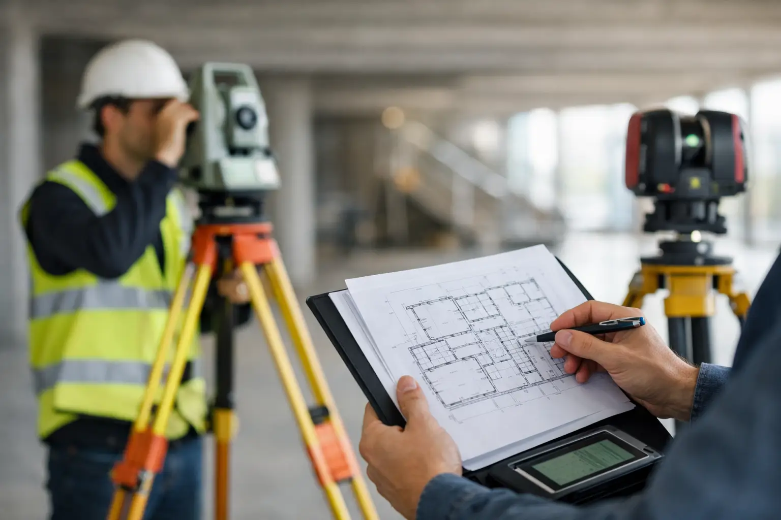
    A digital twin survey workflow succeeds or fails long before any point cloud is processed. If the brief is vague, control is inconsistent or outputs are not matched to operational use, even high-quality capture can produce a model that looks impressive but delivers little value. For survey teams, contractors and asset owners, the real question is not whether to build a digital twin. It is how to create one through a repeatable workflow that supports design, inspection, maintenance and decision-making.

    For most organisations, a digital twin is not a single file or visualisation. It is a structured representation of a real asset or environment, built from reliable survey data and maintained in a form that other teams can use. That may mean a registered point cloud for BIM coordination, a textured mesh for site context, an inspection-grade model for condition assessment, or a combined dataset that supports asset management over time. The workflow matters because every later decision depends on what happened at capture stage.

    What a digital twin survey workflow needs to achieve

    A workable digital twin survey workflow has to balance speed, accuracy, coverage and output requirements. Those priorities change by sector. A heritage project may place more emphasis on geometric fidelity and visual detail. A utilities client may care more about positional confidence, repeat visits and clear asset attribution. A construction team may need rapid turnaround and easy coordination with design models.

    That is why the first stage is definition, not scanning. Before fieldwork begins, the survey specification should set out the required level of detail, tolerances, site constraints, coordinate system, control method, file formats and intended use. If the final deliverable is only described as a 3D model, there is too much room for error. A digital twin intended for clash detection, stockpile measurement and façade inspection will not be captured or processed in the same way.

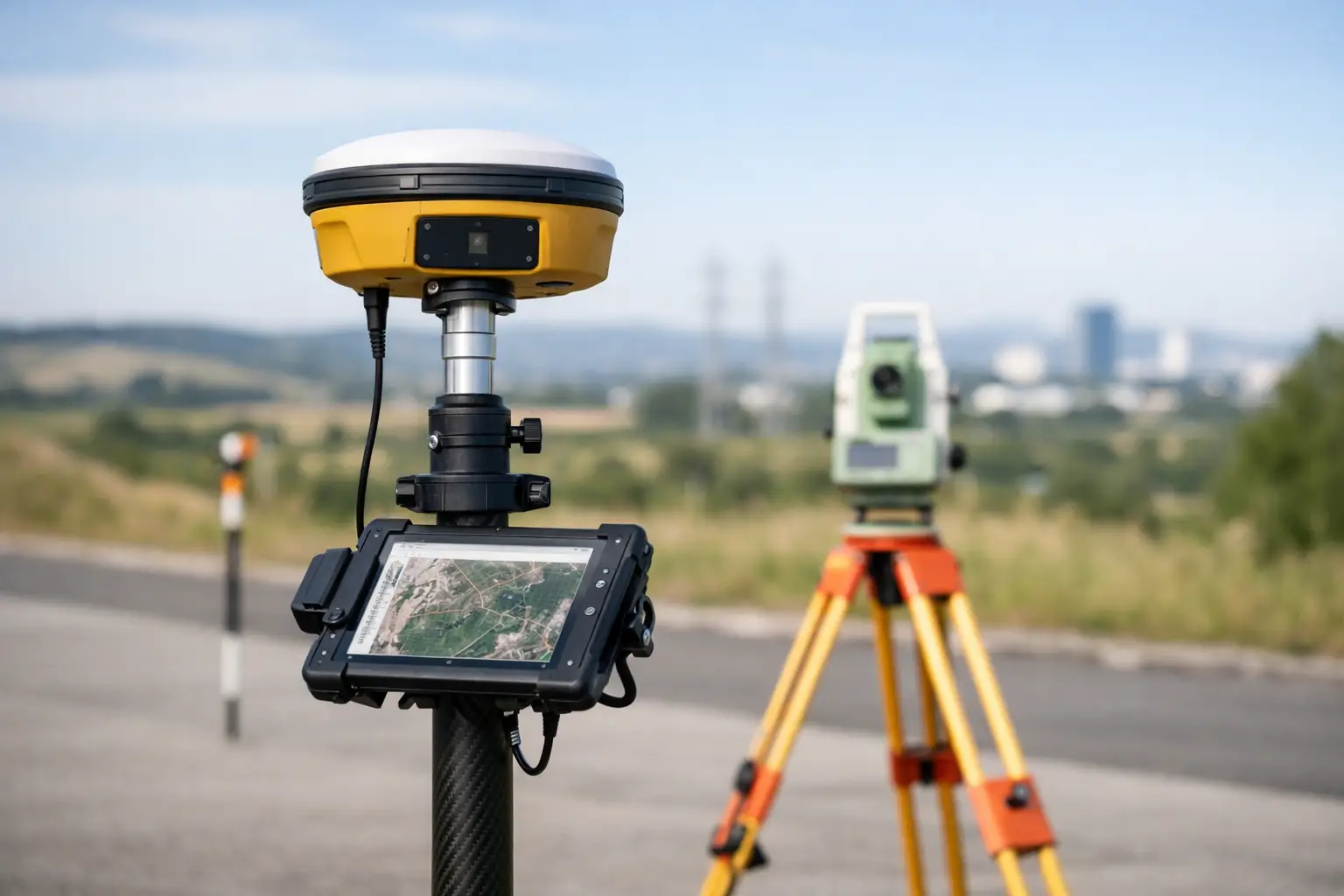
    This early stage is also where equipment choice becomes commercial, not just technical. Static LiDAR, mobile scanning, RTK GNSS, UAV photogrammetry and drone LiDAR each have strengths. No single method is best in every environment. Large external sites often benefit from drone-based coverage and GNSS control, while plant rooms, corridors and complex structures may require terrestrial or handheld LiDAR to achieve suitable density and line-of-sight coverage.

    Planning the digital twin survey workflow on site

    Once the brief is fixed, survey planning becomes a matter of controlling risk. Site access, safety, obstructions, lighting, vegetation, weather and live operations can all affect data quality. A workflow that works well on a vacant development plot may struggle on an active infrastructure site with restricted windows and moving machinery.

    Control strategy is usually where reliable projects separate from rushed ones. If the aim is an accurate and repeatable digital twin, survey control should never be treated as an afterthought. Ground control points, check points and GNSS observations provide the reference needed to place datasets correctly and verify results. In some projects, local coordinates are enough. In others, especially where the model will support broader asset management or future revisits, tying the survey to a recognised grid is the better decision.

    Coverage planning also needs discipline. Overlap is essential, but excessive duplication increases processing time without always improving the final model. The right approach is to plan capture paths and scanner positions around surfaces that matter, areas of occlusion and the required output resolution. Survey teams who understand downstream use will make better field decisions than teams focused only on collecting as much data as possible.

    Capture methods and where each fits

    The capture stage of a digital twin survey workflow is usually a blend of technologies rather than a single instrument pass. Terrestrial LiDAR remains strong for high-detail structural capture, especially where geometry is complex and access is controlled. Mobile LiDAR can improve efficiency across long corridors, road sections, warehouses and large building interiors where speed is important. Drone photogrammetry is often the most cost-effective choice for roofs, elevations, quarries, earthworks and broad topographic context. Drone LiDAR becomes more attractive when vegetation penetration, difficult terrain or reduced dependence on image texture are important.

    There are trade-offs in every combination. Faster capture can mean more noise, more drift risk or lower feature detail. Higher accuracy often means more control, more setup time and more deliberate coverage planning. Dense point clouds can be valuable, but only if the density supports a clear purpose. Capturing millions of extra points that no one uses is rarely efficient.

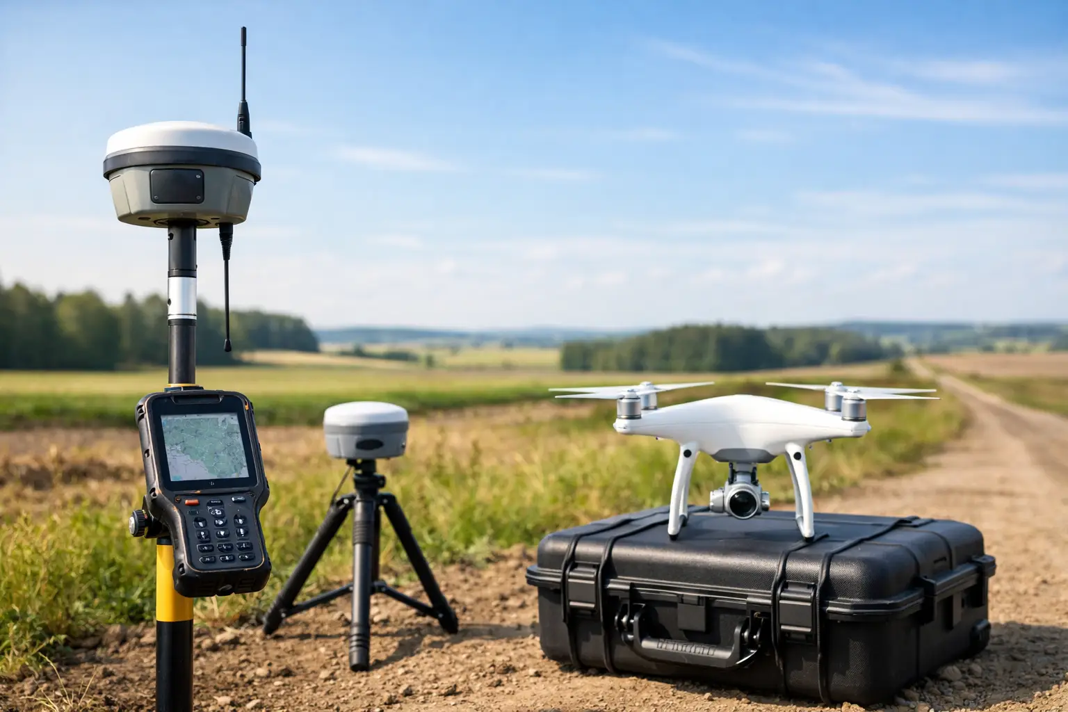
    For many UK projects, a hybrid workflow gives the best result. GNSS and RTK establish control. UAVs cover inaccessible or large external zones. LiDAR scanners capture detail in structures and critical assets. The result is a more complete digital twin, but it also places more pressure on registration and quality assurance later in the workflow.

    Processing, registration and quality control

    Processing is where raw survey data either becomes a dependable digital asset or starts to lose credibility. Registration is not just a software task. It is a quality-critical step that determines whether multiple scans, flights or sessions align correctly enough for the intended use.

    Good registration practice combines automated tools with survey judgement. Cloud-to-cloud methods can be efficient, but they should not replace control and verification where accuracy matters. Residuals, check points and independent comparisons all help confirm whether the dataset performs to specification. If the model will support design coordination or dimensional extraction, small registration errors can become expensive later.

    Noise reduction, classification and cleaning also need restraint. Over-processing can remove useful features or smooth geometry that should remain sharp. Under-processing leaves clutter that affects modelling and interpretation. The right balance depends on the deliverable. An engineering survey for measured dimensions requires a different treatment from a visual digital twin for stakeholder review.

    At this stage, metadata matters more than many clients realise. Recording when the site was surveyed, what control was used, which areas were excluded and what tolerances were achieved helps protect the long-term value of the dataset. A digital twin is only as trustworthy as the information that supports it.

    Turning survey data into usable deliverables

    The strongest digital twin survey workflow does not stop at a registered point cloud. It translates survey data into outputs that other teams can use without reinterpretation. Depending on the brief, that could include CAD linework, BIM-ready models, terrain surfaces, orthomosaics, inspection imagery, cross-sections, feature extractions or mesh models.

    This is where many projects either generate operational value or create friction. If design teams receive data in the wrong format, or asset managers receive a model with no meaningful structure, the digital twin becomes a visual archive rather than a working resource. Output specification should therefore reflect software environment, naming conventions, level of detail and update requirements from the start.

    It also helps to distinguish between visual completeness and survey suitability. A polished model can still be weak for measurement if control and accuracy are not proven. Equally, a point cloud that looks less refined on screen may be the better engineering deliverable if its positional quality is well evidenced.

    Why workflow design affects long-term asset value

    A digital twin has more commercial value when it can be updated, compared and reused. That depends on consistency. If each survey visit uses different control, different capture extents or different modelling assumptions, change detection becomes difficult and confidence drops. Repeatability is what turns one survey into an operational dataset.

    For infrastructure, utilities, estates and industrial sites, the long-term benefit often comes from this repeatability rather than from the initial model alone. Once a survey workflow is standardised, future inspections, expansion works and compliance checks become faster and more defensible. The asset owner is no longer starting from zero every time conditions need to be assessed.

    That is also why service support and implementation guidance matter. The right hardware can significantly improve field efficiency, but equipment on its own does not create a reliable digital twin workflow. Teams need suitable control methods, processing discipline, output standards and practical training. For organisations building internal capability, or for those outsourcing delivery, the best results come from aligning technology with a clear survey method rather than treating the digital twin as a software problem.

    For buyers assessing options, the useful question is simple: will this workflow produce repeatable, analysis-ready data for the way the asset will actually be managed? If the answer is unclear, the specification needs more work before the first scan is taken.

    A digital twin should reduce uncertainty, not add another layer of it. When the survey workflow is planned properly, the outcome is not just a model. It is a dependable spatial record that supports faster decisions, safer operations and better control over the asset long after the site team has left.

  • Guide to Measured Building Surveys

    Guide to Measured Building Surveys

    A refurbishment stalls quickly when the drawings do not match the building. Door openings are out by 40 mm, floor levels vary room to room, and a ceiling void hides services no one expected. That is usually when a guide to measured building surveys stops being a nice-to-have and becomes a project requirement.

    Measured building surveys provide the dimensional record needed to design, plan, cost and manage work with confidence. For architects, contractors, estates teams and asset owners, the value is simple: fewer assumptions, fewer site returns, and a clearer basis for decisions. The right survey approach can save significant time later, but only if the scope, accuracy and outputs are properly aligned to the job.

    What a guide to measured building surveys should cover

    At its core, a measured building survey captures the physical geometry of a structure and turns it into usable information. That normally includes floor plans, elevations, sections and, where required, reflected ceiling plans or 3D models. Depending on the brief, it may also record structural elements, openings, floor level changes, roof forms, service features and external details.

    The point is not just to measure a building. It is to produce reliable, CAD-ready or model-ready data that supports the next stage of work. For a fit-out contractor, that may mean accurate internal plans. For a heritage consultant, it may mean detailed elevations and sections. For an asset manager, it may be a 3D record that can be reused across maintenance and lifecycle planning.

    A common mistake is to treat all measured building surveys as broadly the same. They are not. A simple office floor for lease planning is very different from a listed property with irregular geometry, restricted access and a requirement for high-detail elevations. Scope drives method, cost and programme.

    When a measured building survey is needed

    Most projects call for a measured survey when existing information is incomplete, outdated or unreliable. That is common in older buildings, multi-phase sites, altered interiors and operational estates where drawings have not kept pace with change.

    Typical use cases include refurbishment, extension design, space planning, facade assessment, heritage recording, dilapidations support, fire strategy updates and change-of-use projects. Building owners also commission surveys before disposal, acquisition or major maintenance planning, especially where downstream teams need dependable base information.

    There is also a practical risk point here. If multiple consultants work from inconsistent records, coordination problems appear early. Mechanical layouts clash with structure, ceiling heights are misread, and stair geometry causes compliance issues. A well-specified survey reduces that risk before it spreads through design and construction.

    Survey methods and where each one fits

    Traditional total station and tape-based methods still have a place, particularly for straightforward or smaller jobs. They can be effective where access is easy and the required output is limited. The trade-off is speed and completeness. Manual capture is more selective by nature, so omissions are more likely if the brief is not tightly controlled.

    Laser scanning has become central to modern measured building surveys because it captures dense spatial data quickly and with a high level of detail. Complex interiors, irregular facades, plant areas and multi-level environments benefit most. A point cloud gives the project team a far richer reference set than isolated measured points, which is particularly useful when designs evolve after the site visit.

    Mobile mapping and handheld LiDAR can also add value, especially where speed on site matters or access conditions make static setups less efficient. That said, suitability depends on required accuracy, geometry complexity and final deliverables. Faster capture is not automatically the best option if the end use demands stricter tolerances or highly controlled outputs.

    Photogrammetry can support facade work, roof areas and visually complex heritage environments, often alongside laser scanning rather than instead of it. In many projects, the strongest workflow is hybrid: the method is chosen around the building, the brief and the accuracy requirement, not the other way round.

    Accuracy, tolerance and level of detail

    Accuracy is one of the first questions buyers ask, and rightly so. But it needs context. There is no single “accurate enough” standard for every building survey. A layout for general space planning may tolerate less detail than fabrication support, conservation documentation or intrusive structural coordination.

    What matters is agreeing expected tolerances at the start. That should cover not only measurement accuracy, but also what is being represented in the final output. For example, are skirtings, beams, soffits, service penetrations or visible structural distortions to be shown? Are floor levels required throughout or only at key thresholds? Is roof geometry needed for design, or simply for outline reference?

    Level of detail directly affects both field time and processing time. More detail is not always better. If a client commissions a highly detailed survey for an early feasibility stage, they may be paying for information that will not be used. Equally, under-specifying a survey can create a false economy if teams later need revisits to capture missing elements.

    Outputs: what clients should expect

    The most common deliverables are 2D floor plans, elevations and sections in CAD format, often supported by PDF issue sheets. For many commercial and public-sector projects, that is still the most practical baseline.

    However, 3D outputs are increasingly requested, especially for coordination, visualisation and estate data reuse. Depending on the requirement, this may mean a registered point cloud, a Revit model, or a structured 3D representation built to an agreed level of information need. Not every project needs BIM-ready outputs, but where future phases depend on coordinated digital records, 3D can provide a much stronger long-term asset.

    Clients should also be clear about file compatibility and naming conventions. A technically strong survey loses value if the design team cannot integrate the data easily. Output requirements should therefore include formats, layering standards, control information and any project-specific modelling conventions.

    What affects cost and programme

    Survey pricing is shaped by more than building size. Complexity of geometry, number of levels, access restrictions, occupancy, required control, output detail and programme constraints all influence cost. So does site condition. A clean, vacant floorplate is much faster to capture than an occupied healthcare environment or a live industrial facility.

    Programme depends on both site capture and office processing. Clients sometimes underestimate the production stage, especially for detailed elevations, sections and 3D models. Capturing the data may take a day or two, but validation, registration, drafting and quality assurance can take considerably longer.

    There is also a commercial decision around timing. Early survey appointment often improves design efficiency because the team works from verified geometry from the outset. Delaying the survey to save budget can push uncertainty into later stages where design changes cost more.

    Choosing the right survey partner

    A measured building survey is only as useful as the team delivering it. Technical capability matters, but so does project understanding. The best survey partner will ask focused questions about end use, tolerances, constraints and downstream deliverables before proposing a method.

    For professional buyers, the key checks are straightforward. Can the supplier demonstrate experience with similar building types? Do they have the right capture technology for the site conditions? Can they produce outputs that fit your CAD or BIM workflow? Do they have the capacity to support urgent programmes or phased delivery if needed?

    It is also worth assessing whether the provider can support beyond data capture. On more complex projects, value comes from a joined-up service – fieldwork, processing, quality control, technical advice and, where needed, additional geospatial support. That is often where a specialist provider such as LiDAR Tech UK offers a commercial advantage, particularly for organisations that need both survey delivery and access to modern spatial capture technology.

    Common problems and how to avoid them

    Most issues with measured building surveys begin before anyone goes to site. The brief is vague, key areas are omitted, or stakeholders assume someone else has defined the required output. The result is usually rework.

    A better approach is to lock down purpose, survey extent, level of detail, access arrangements and file requirements at the start. If there are sensitive areas, restricted working hours, occupied zones or health and safety controls, these should be addressed in the survey planning stage rather than on the day.

    Clients should also be realistic about hidden conditions. A measured survey records what is visible and accessible at the time of capture unless the brief specifically includes intrusive investigation. Ceiling voids, concealed structure and covered service runs often need separate investigation if they are critical to design.

    Guide to measured building surveys for better project decisions

    The strongest reason to commission a measured building survey is not simply to obtain drawings. It is to reduce uncertainty. Accurate spatial data supports better design decisions, clearer coordination, tighter quantities and fewer surprises on site.

    That benefit is highest when the survey is specified properly. Match the method to the building, match the detail to the project stage, and make sure the outputs fit the way your team actually works. If you get those decisions right at the beginning, the survey becomes more than a record of the existing structure – it becomes a dependable base for everything that follows.

    If your project depends on accurate building geometry, the right time to define the survey is before assumptions make their way into design.

  • Survey Control Network Setup That Holds Accuracy

    Survey Control Network Setup That Holds Accuracy

    A control point that shifts by a few millimetres can become a very expensive problem once machine control, setting out, LiDAR registration or drone mapping all depend on it. That is why survey control network setup is not an administrative prelude to site work. It is the framework that determines whether every subsequent dataset agrees, scales correctly and stands up to scrutiny.

    For contractors, consultants and asset owners, the issue is rarely whether control is needed. The real question is how much control is enough for the site, the specification and the programme. A small topographical survey on open ground does not need the same network design as a rail corridor, a deformation monitoring scheme or a multi-phase construction project where different teams return to site over several months.

    What a survey control network setup needs to achieve

    At a practical level, a control network must do three things well. It must provide positions that are accurate enough for the intended deliverable, remain stable for the life of the project and be recoverable by more than one crew or instrument.

    That sounds straightforward, but performance depends on several linked decisions. Station spacing affects geometry. Monument type affects long-term reliability. Observation method affects achievable precision. Processing and adjustment affect whether errors are exposed or hidden. If one part is weak, the whole network becomes harder to trust.

    For most professional projects, the target is not simply to create a series of coordinates. The target is to establish a control environment that supports total stations, GNSS rovers, laser scanners, mobile mapping systems and drones without introducing avoidable discrepancies between platforms.

    Start with purpose, not equipment

    A good survey control network setup starts with the end use of the data. If the output is a boundary survey tied to a national grid, the control strategy will differ from one designed for internal construction coordination. If the project includes scan-to-BIM, façade monitoring or volumetric measurement, vertical control may matter just as much as horizontal control.

    This is where many avoidable errors begin. Teams sometimes choose a method because the kit is available rather than because the project requires it. RTK GNSS may be efficient on open sites with good sky visibility, but it is less dependable around tall structures, heavy tree cover or reflective surfaces. A traversed total station network may deliver stronger local geometry, but it takes more field time and benefits from careful closure design. Static GNSS can tie a site into a wider reference frame very effectively, but it may be excessive for short-duration works where local relative accuracy is the priority.

    The right approach is usually a combination. Primary control may be established with static GNSS or tied to known references, while secondary control is densified with total station observations to suit the site layout. That blended method often gives the best balance between absolute positioning and practical usability on site.

    Planning the network geometry

    Geometry matters more than many project teams realise. Well-placed stations create redundancy and make blunders easier to detect. Poorly placed stations produce a network that appears complete on paper but is fragile in practice.

    Stations should be intervisible where possible, with lines that avoid long narrow chains of dependent points. A single linear traverse can be acceptable in constrained corridors, but it carries more risk than a network with loops and cross ties. On larger sites, enclosing the work area with control and adding internal checks generally produces more reliable results than pushing control progressively outward from one starting point.

    Station location also needs practical judgement. A point that is theoretically ideal but likely to be disturbed by earthworks, resurfacing or plant movement is a bad investment. Permanent marks should sit outside likely construction impact zones while remaining convenient enough that crews will actually use them. There is no value in a perfect control mark if accessing it adds an hour to every visit.

    Primary and secondary control

    It helps to separate the network by function. Primary control should consist of the most stable, best-observed points on site. These points anchor the wider framework and should be protected accordingly. Secondary control can then support daily operations such as detail survey, scanning set-up or setting out.

    This distinction is especially useful on active construction sites. Secondary points are more exposed to damage and may need replacing. If the primary framework is sound, secondary control can be rebuilt without compromising the overall coordinate integrity of the project.

    Observation methods and trade-offs

    No single method is best in every environment. GNSS is fast and efficient, especially when linked to reliable correction services, but performance depends on satellite visibility, multipath conditions and communications. Total stations provide excellent relative precision and remain indispensable where line-of-sight observations are manageable. Laser scanning can support local registration control, but it should not replace a properly designed control network when traceable accuracy is required.

    A common commercial mistake is assuming that faster data capture offsets weaker control. It rarely does. If control is inconsistent, the time saved in the field is often lost in rework, alignment issues, failed quality checks or disputes over tolerances. On high-value projects, dependable control is usually one of the lowest-cost ways to reduce downstream risk.

    Datum, projection and height control

    Coordinate systems need explicit agreement at the start. National Grid, local grid, site grid and engineering grid all have their place, but mixing them carelessly creates confusion very quickly. The same applies to heights. Teams must know whether they are working with orthometric heights, ellipsoidal heights or a transformed site-specific height model.

    This is not just a processing detail. If the site uses multiple subcontractors, machine control providers and remote sensing workflows, a shared understanding of datum and projection prevents costly misalignment between datasets. A point cloud that is accurate in itself can still be commercially useless if it is delivered in the wrong frame.

    Quality control during survey control network setup

    Quality assurance should be built into the fieldwork, not added afterwards. Independent checks, repeat occupations and loop closures are what turn observations into trusted control. If a point is occupied once and accepted without redundancy, the network may be fast to establish but difficult to defend.

    Adjustment is equally important. Least squares adjustment is not simply a reporting formality. It helps identify residuals, weak geometry and observations that deserve scrutiny. Professional buyers increasingly expect this level of rigour because the control may support legal boundaries, design coordination or payment quantities.

    Tolerance should always be linked to project need. There is no universal figure that suits every survey. A highway scheme, a utilities as-built survey and a heritage recording project each have different accuracy demands. Over-specifying can waste time and budget. Under-specifying is usually more expensive later.

    Common reasons control networks fail

    Most failed networks do not fail because of one dramatic mistake. They fail because small assumptions go unchallenged. A mark is set in an unstable location. A transformation is applied without proper validation. A GNSS fix is accepted in marginal conditions. Secondary control is treated as permanent. Field notes are incomplete, so future crews cannot verify what was done.

    Another common issue is poor handover between teams. If surveyors, drone operators, scanning specialists and engineers are not working from the same control logic, discrepancies emerge that look like software problems but are actually control problems. Clear control reports, point schedules, sketches and method statements are part of the technical solution, not optional paperwork.

    Making control work across modern geospatial workflows

    Projects now depend on more than one instrument type. A network may need to support RTK rovers for topographical work, total stations for setting out, terrestrial LiDAR for detailed capture and drones for coverage at scale. The control strategy should anticipate that from the outset.

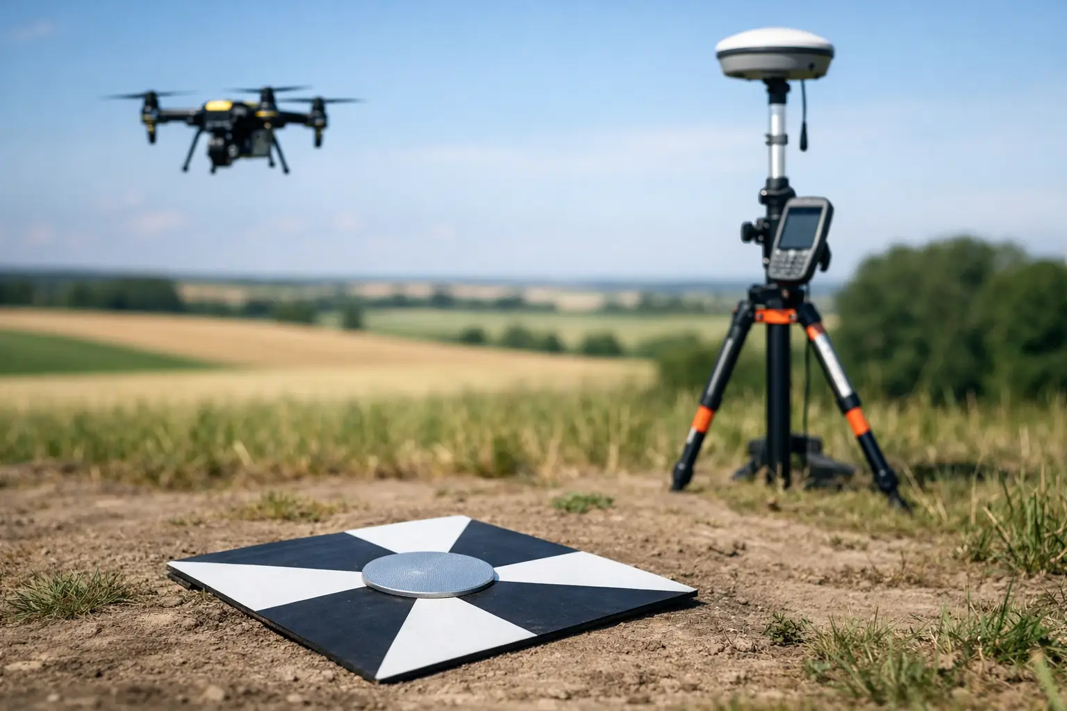
    For example, scanner targets and check points should be placed where they help registration without compromising the integrity of the wider framework. Drone ground control should be distributed for geometry rather than clustered where access happens to be easiest. Construction teams may need local working points, but those points should still resolve back to the primary network cleanly.

    This is where a joined-up provider adds value. LiDAR Tech UK supports organisations that need hardware, technical guidance and field-ready workflows to work together rather than operate as separate purchases. For many clients, that reduces the gap between specification and real-world deployment.

    When to redesign rather than extend

    There is a point where extending an ageing network becomes less efficient than redesigning it. If site conditions have changed, if several stations have been lost, or if the project scope now demands higher precision than originally planned, adding more patches can create confusion. A partial reset with clear control hierarchy is often the better commercial decision.

    The same applies when a project shifts from one phase to another. Early earthworks control may not be sufficient for structural steel, façade installation or deformation monitoring. Each phase should be assessed against current tolerance, access and programme requirements rather than assuming the original setup remains suitable.

    A well-designed control network does not attract much attention on a good day, and that is precisely the point. It lets every survey, scan and set-out task proceed with confidence. If you are planning new works, introducing GNSS or LiDAR workflows, or trying to bring consistency across multiple crews, getting the control right first will save far more than it costs.

  • How to Process Drone Point Clouds

    How to Process Drone Point Clouds

    A dense point cloud is only useful if it becomes a dependable deliverable. Many drone surveys fail at the desk rather than in the air – not because the flight data was poor, but because the processing workflow was inconsistent, over-smoothed, or not set up for the final output. If you need to know how to process drone point clouds for survey, inspection, or modelling work, the key is to treat processing as part of the survey method, not an afterthought.

    The right workflow depends on the sensor, the required accuracy, and the deliverable. A stockpile survey, a utility corridor, and a façade inspection all place different demands on classification, noise filtering, control, and export settings. That is why the best processing approach is not the one with the most automation. It is the one that preserves accuracy while producing usable data quickly.

    How to process drone point clouds: start with the end use

    Before importing anything, define what the point cloud needs to become. If the client needs a DTM for earthworks calculations, your priorities will be ground classification, vegetation removal, and reliable control. If the output is a 3D mesh for asset visualisation, surface completeness may matter more than a bare-earth model. For measured building work, edge fidelity and registration quality become more important than raw density.

    This decision affects the whole chain – flight planning, overlap, control strategy, sensor settings, software choice, and export format. Processing is far more efficient when the specification is clear from the start.

    In practical terms, identify the required coordinate system, expected tolerance, coverage area, and final deliverables before you begin. A professional workflow should also confirm whether the job requires LAS, LAZ, E57, RCP, mesh, contours, DSM, DTM, orthomosaic, or CAD-ready linework. Too many reprocessing cycles happen because that question was left until the end.

    Import, organise and verify the raw data

    The first desk-based stage is data integrity. Bring in the raw files, but do not process immediately. Check that all flight logs, image sets, LiDAR data, IMU records, and GNSS information are present and complete. If RTK or PPK has been used, verify that the corrected positioning solution is valid and that timestamps align properly across the dataset.

    Good file organisation matters more than many teams admit. Separate raw data from processed outputs, preserve original filenames, and document control coordinates, site notes, and flight metadata. On larger projects, that discipline saves time and reduces avoidable errors.

    At this stage, carry out a visual check. Look for missing strips, blurred imagery, poor overlap, excessive variation in flying height, or obvious GNSS issues. If the point cloud comes from LiDAR rather than pure photogrammetry, inspect trajectory quality and scan consistency before moving into full processing.

    Align the dataset correctly

    Alignment is where accuracy is won or lost. For photogrammetry, this means camera alignment and tie-point generation. For LiDAR, it usually means trajectory processing, strip adjustment, and registration. In hybrid workflows, it can mean combining both.

    If you are processing imagery-based point clouds, use high-quality overlap and sound camera calibration data. Ground control points and check points should be imported early, with the correct coordinate system and height datum. Control should not be used blindly. Spread it across the site, include changes in elevation, and keep independent checks aside to test the solution.

    For LiDAR workflows, pay attention to boresight calibration, IMU quality, GNSS corrections, and any drift along longer corridors. Strip alignment tools can improve consistency, but they should not be used to mask poor acquisition. If the source trajectory is weak, processing can only do so much.

    This is also the point to review residuals. Low residual values are encouraging, but they are not the whole story. You still need to inspect the model spatially. A dataset can report acceptable statistics while showing localised deformation near edges, vegetation, reflective surfaces, or uniform textures.

    Clean noise before heavy editing

    Every point cloud includes unwanted data. The trick is to remove noise without stripping out valid geometry. Over-aggressive filtering may leave you with a neat-looking model that no longer represents the site properly.

    Start with obvious outliers such as isolated airborne points, duplicated returns, and data beyond the survey boundary. Then assess whether the noise is random or systematic. Random noise often comes from vegetation movement, poor lighting, or marginal surfaces. Systematic noise may point to calibration issues, poor registration, or weak control.

    For drone LiDAR, classify low, medium, and high noise separately if the software allows it. For photogrammetric clouds, inspect vertical surfaces, water, glass, and repetitive textures carefully. These are common problem areas. It is usually better to clean in stages, checking each pass, than to apply one heavy filter and hope for the best.

    Classify the cloud to suit the job

    Classification turns a mass of points into something usable. Ground, buildings, vegetation, roads, powerlines, and site objects may all need separate classes depending on the application. The right setup depends on what the client needs to measure.

    For topographic survey work, the ground class is the priority. That means tuning parameters to remove scrub, parked plant, fences, and low structures without cutting into embankments or hard edges. In forestry, canopy structure may be the main value, so preserving multiple returns and vegetation classes becomes more important than producing a perfectly clean terrain model. For inspection work, classification may be minimal if the objective is simply a registered 3D dataset for viewing and measurement.

    Automation speeds this stage up, but it still needs manual review. Ground algorithms can struggle with steep banks, retaining walls, kerb lines, rubble, and dense undergrowth. If the terrain matters commercially, human quality control is still essential.

    Build the required surfaces and models

    Once the cloud is clean and classified, generate the products that suit the brief. A DSM includes everything visible from above, while a DTM aims to represent the bare earth. That distinction matters for cut-and-fill analysis, flood modelling, route design, and planning work.

    If you need a TIN or mesh, check whether the point density supports the level of detail expected. Very dense clouds are not always better. They can increase processing time, file size, and software instability without improving the final model. Decimation can be sensible, especially for visualisation or collaboration, but only if it does not compromise measurement quality.

    Orthomosaics, contours, breaklines, and CAD-ready exports often sit alongside the point cloud rather than replacing it. This is where specification-driven processing pays off. You should only create what the project actually requires.

    Quality check against control and site reality

    A professional output needs more than a quick screen review. Test the point cloud against check points, independent survey control, and known site dimensions. Where possible, compare sections through hard surfaces, building corners, kerbs, and other measurable features.

    Look at relative as well as absolute accuracy. A cloud can be well tied to national grid coordinates but still show local distortion. Equally, a visually clean model may contain classification errors that affect volume calculations or design inputs.

    For commercial survey work, document the QA process. Record the control method, processing settings, residuals, classification approach, and any known limitations. That record protects both the supplier and the client, especially where the data will inform design, construction, or asset decisions.

    Export point clouds in the right format

    Export is not just a final click. The format, coordinate system, class structure, and file size all affect whether the dataset is useful downstream. LAS and LAZ are common for classified point clouds. E57 is often useful for interoperability. Some clients need Autodesk-compatible outputs, while others want a simple deliverable for GIS or volume software.

    Keep units, projection, and metadata consistent. If the cloud is split into tiles, name them clearly and use a logical grid. If colour information is required, confirm that it has been retained properly. If the client needs classification codes, test the export in the receiving software before issuing the final files.

    This is also the stage to create lighter derivatives for routine viewing. A full-resolution master cloud should be preserved, but many teams also benefit from reduced-size copies for faster handling in common desktop applications.

    How to process drone point clouds efficiently at scale

    When projects become larger, speed matters as much as accuracy. The answer is standardisation. Build repeatable templates for control import, classification settings, QA checks, file naming, and export profiles. That reduces operator variation and makes turnaround more predictable.

    It also helps to match software and hardware to the sensor type. LiDAR-led workflows typically benefit from tools built for trajectory processing and classification. Image-led workflows may place more demand on GPU resources and alignment settings. There is no single best software stack for every project. It depends on the sensor, the site, and the output standard.

    For organisations running regular survey or inspection work, training is often the difference between acceptable results and dependable ones. LiDAR Tech UK supports clients not only with hardware selection but with workflows that fit operational requirements, which is often where the real value sits.

    Processing drone point clouds well is not about pushing every dataset through the same automated routine. It is about making sensible technical decisions at each stage so the final output stands up in the field, in the office, and in front of the client.

  • RTK vs PPK Mapping: Which Fits Best?

    RTK vs PPK Mapping: Which Fits Best?

    When a site programme is tight and the deliverable has to stand up to scrutiny, the RTK vs PPK mapping decision is not academic. It affects how quickly you can mobilise, how much field control you need, and how much confidence you have in the final coordinates. For surveyors, drone operators and engineering teams, the right choice usually comes down to project risk, correction availability and the way your team actually works on site.

    RTK vs PPK mapping in simple terms

    RTK, or Real-Time Kinematic, applies correction data during the survey or flight. The rover or drone receives live corrections from a base station or network service, then fixes positions in real time. That gives you immediate feedback and allows data capture with survey-grade positioning while the work is being carried out.

    PPK, or Post-Processed Kinematic, records raw GNSS observations during the job and applies corrections later in the office. Instead of relying on a continuous live link during capture, you process the trajectory afterwards against base data or reference observations. The practical result is similar in ambition – high-accuracy positioning – but the workflow, risk profile and site requirements are different.

    For professional mapping, that difference matters. One method prioritises real-time certainty in the field. The other gives you more flexibility when communications are unreliable or the environment is difficult.

    Why the choice matters on real projects

    On a straightforward stockpile survey in an area with good mobile coverage, RTK may be the quickest option. You can fly, confirm solution status on site and move straight into processing. If the objective is speed with minimal rework, that is hard to ignore.

    On a linear infrastructure corridor, forestry site or remote utility route, the picture changes. Signal interruptions, uneven canopy, terrain masking and poor network access can all affect a live correction stream. In those cases, PPK often gives teams more resilience because the survey does not depend on maintaining a constant correction link throughout the operation.

    That is why there is no universal winner in RTK vs PPK mapping. Accuracy alone does not settle it. You also need to consider field conditions, operational pressure and what happens if something fails halfway through the job.

    Accuracy expectations: RTK vs PPK mapping

    Both methods can support centimetre-level results when deployed correctly. In practice, final accuracy depends on GNSS visibility, baseline length, quality of control, sensor calibration, flight planning and processing discipline. The positioning method is only one part of the chain.

    RTK can perform extremely well when the correction source is stable and the fix quality is maintained throughout the mission. If your drone or rover holds a reliable fixed solution and your control checks agree, the output can be very efficient and highly dependable.

    PPK can be equally strong, and in some scenarios more forgiving. Because you process afterwards, you can inspect the data quality in detail, reject poor epochs and work with a fuller view of what happened during the mission. That can be useful where live correction interruptions would otherwise create uncertainty.

    The important point for commercial buyers is this: neither RTK nor PPK removes the need for sensible survey control and validation. If the job carries contractual, engineering or legal weight, independent checks remain essential.

    Where RTK has the advantage

    RTK suits teams that need immediate positional confidence during capture. On active construction sites, quarries, development land and routine topographical work, that can reduce wasted time. You know in the field whether you have a fixed solution, whether the system is behaving as expected and whether a re-flight is needed before demobilisation.

    It also simplifies some workflows. If your equipment integrates well with a correction service and your team follows consistent setup procedures, RTK can reduce the burden of office-based trajectory processing. For busy operators managing repeat surveys across multiple sites, that efficiency has clear value.

    RTK also works well when your client expects a fast turnaround and the site environment is controlled enough to support it. If mobile data coverage is stable or a local base can be established easily, real-time correction is often the cleanest route.

    Where PPK has the advantage

    PPK comes into its own when field conditions are less predictable. Remote sites, poor mobile coverage, partial sky obstruction and long corridors all make live corrections harder to trust. With PPK, the mission can proceed without depending on a continuous correction feed.

    That can reduce operational stress. Instead of constantly monitoring whether the link has dropped out, the team focuses on consistent capture, sound base data and proper post-processing. For organisations surveying infrastructure, forestry, utilities and rural assets, that flexibility can be a decisive benefit.

    PPK is also attractive where data auditability matters. Because the trajectory is processed afterwards, there is often more opportunity to review and document what happened. For some clients and quality systems, that additional traceability is valuable.

    Ground control points still matter

    A common mistake in discussions about RTK vs PPK mapping is treating both as a complete replacement for ground control. In reality, reduced control does not mean zero control.

    RTK-enabled and PPK-enabled workflows can cut the number of ground control points needed for mapping, especially with well-calibrated sensors and disciplined procedures. That saves time on hazardous or difficult sites. But check points are still vital for validating horizontal and vertical accuracy.

    If the terrain is complex, the site is large, or the output will feed into design, volume calculations or compliance documentation, independent checks are not optional. Good practice is not just about claiming a specification. It is about proving that the delivered data meets it.

    Workflow, risk and team capability

    The better question is often not which method is more accurate, but which method introduces less risk for your operation.

    RTK shifts confidence to the field stage. If the corrections are sound and the fix remains stable, you leave site with a strong idea of data quality. The trade-off is dependency on communications and setup discipline. A weak network, poor base placement or unnoticed fix issue can undermine the result quickly.

    PPK shifts more responsibility to the office stage. You gain flexibility during capture, but you need a team that can manage raw data properly, process trajectories correctly and maintain a documented workflow. If that capability is missing, the advantage of PPK can be lost in rework or inconsistent outputs.

    This is where equipment choice and supplier support matter. Integrated GNSS, drones, correction services and processing software reduce friction, but only if the workflow is properly understood. For many organisations, a dependable support partner matters as much as the specification sheet.

    Which method suits which project?

    For construction progress mapping, routine earthworks, site stockpiles and many standard topographical drone surveys, RTK is often the practical first choice. It is fast, efficient and well suited to teams working to tight operational windows.

    For remote land surveys, utility corridors, forestry mapping and sites where coverage is unreliable, PPK often provides more resilience. It lets teams capture data without hinging success on a live correction feed.

    For higher-stakes projects, many professionals use a blended mindset rather than a rigid preference. They choose hardware that supports both approaches, apply proper check points and decide on the day based on signal conditions, site access and project tolerances. That is usually the most commercially sensible position.

    Making the right decision

    If your priority is speed in the field, straightforward workflows and immediate quality visibility, RTK is usually the stronger fit. If your priority is flexibility, resilience in difficult environments and reduced dependence on live connectivity, PPK may be the better option.

    For UK organisations investing in drone mapping or GNSS survey capability, the best decision comes from matching the method to the project environment, the required deliverable and your internal capacity to process and verify results. LiDAR Tech UK typically sees the strongest outcomes where clients assess the full workflow rather than chasing a headline feature.

    The useful test is simple: choose the method that gives you reliable coordinates with the least operational risk, not the one that sounds more advanced on paper.

  • LiDAR Tunnel Mapping Services Explained

    LiDAR Tunnel Mapping Services Explained

    When a tunnel survey has to be completed during a tight possession window, every minute matters. LiDAR tunnel mapping services give asset owners, contractors and survey teams a faster way to capture accurate 3D geometry in confined, low-light and operationally sensitive environments where traditional methods can quickly become slow, disruptive and costly.

    Where LiDAR tunnel mapping services add value

    Tunnels are difficult survey environments by default. GNSS is unavailable, visibility can be poor, access may be restricted, and safe working time is often limited by operations. At the same time, the need for dependable data is high. Rail tunnels, highway bores, utility corridors, culverts, mines and service passages all require precise measurement for inspection, clearance analysis, maintenance planning and design validation.

    LiDAR tunnel mapping services are well suited to these conditions because they capture dense point cloud data rapidly across long linear assets. Instead of relying on discrete measured points, project teams receive a full 3D record of the tunnel lining, track bed, cable routes, drainage runs, service penetrations and other internal features. That level of detail supports better decision-making when assessing deformation, planning remedial works or coordinating future installations.

    For many organisations, the commercial advantage is just as important as the technical one. Shorter field time can reduce possession costs, lessen operational disruption and improve site safety by limiting the duration surveyors spend in hazardous or access-controlled areas.

    What a tunnel LiDAR survey actually delivers

    A well-executed tunnel survey is not simply about collecting data quickly. The output has to be usable for engineering, design and asset management. That is where specification, control strategy and processing discipline matter.

    Most projects require a registered and georeferenced point cloud, but deliverables can vary depending on the asset and downstream use. A client may need measured cross sections at fixed intervals, clearance envelopes, deformation analysis, digital terrain and track models, 2D drawings, BIM-ready geometry or a textured 3D model for visual review. In some cases, the priority is condition assessment. In others, it is dimensional control for refurbishment, extension or clash detection.

    This is why tunnel mapping should not be treated as a one-size-fits-all scanning exercise. Scanner selection, traverse design, control establishment and data processing all need to align with the required accuracy and final output format.

    Why tunnels need a different survey approach

    The challenge with tunnels is that the environment works against standard survey workflows. Satellite positioning drops out, repetitive surfaces can complicate registration, and dust, moisture or reflective materials may affect data quality. Curved alignments, service recesses and variable lighting can also create blind spots if the capture plan is not thought through properly.

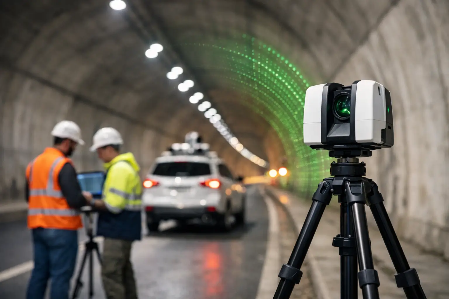
    A practical tunnel LiDAR methodology usually combines mobile or handheld scanning with static control where needed. For long corridors, mobile capture can cover ground efficiently. For areas that demand tighter tolerances, such as portal interfaces, plant rooms, structural defects or complex junctions, static scanning and total station control may still be the right choice.

    That balance matters. Mobile methods are faster, but speed alone is not the goal. If a refurbishment contractor needs millimetre-level confidence for prefabricated components, the survey design has to reflect that. If the objective is condition mapping across a long asset, a different capture strategy may be more cost-effective.

    Accuracy, speed and the trade-off between them

    Professional buyers tend to ask the same question first: how accurate is the data? The honest answer is that it depends on the tunnel, the control available and the purpose of the survey.

    LiDAR tunnel mapping services can achieve highly accurate results, but accuracy should always be defined against project tolerances rather than broad marketing claims. Relative accuracy within a local section may be excellent, while absolute accuracy across a long alignment depends heavily on control, registration and verification. In a tunnel with limited access points and long distances between control stations, maintaining confidence over the full corridor requires careful planning.

    There is also a trade-off between productivity and precision. Rapid mobile scanning can transform field efficiency, especially in rail and utilities environments, but not every job needs the same specification. A project for general asset documentation may prioritise speed and coverage. A project for structural remediation or clearance analysis may justify a slower workflow with denser control and additional validation.

    The right service provider should be clear about that distinction from the outset. Over-specifying a survey increases cost unnecessarily. Under-specifying it creates risk later, usually when design teams start relying on the data.

    Typical use cases across UK infrastructure

    In the UK market, tunnel scanning is increasingly used across transport, utilities and civil engineering projects where downtime is expensive and access is difficult. Rail operators and contractors use LiDAR for gauging, lining assessment, drainage review, cable route documentation and pre-work planning. Highway teams use it to document road tunnels, service bays, ventilation areas and structural elements prior to maintenance or upgrade works.

    Utility and infrastructure managers also benefit from 3D tunnel data when recording pipework, conduits, cable trays and associated access points. Where legacy drawings are incomplete or unreliable, a current measured dataset can significantly reduce uncertainty before intrusive works begin.

    Heritage and conservation projects are another strong fit. Historic tunnels and underground structures often have irregular geometry that is difficult to capture with traditional methods alone. LiDAR provides a detailed digital record that supports restoration, monitoring and long-term documentation.

    What to look for in a service provider

    Choosing between lidar tunnel mapping services is not just about who owns a scanner. It is about who can plan the survey properly, work safely in restricted environments and deliver data in a format your team can use immediately.

    Start with methodology. A credible provider should explain how they will establish control, manage registration, verify accuracy and deal with known tunnel constraints such as poor lighting, repetitive surfaces and access limitations. They should also be clear on whether the project is best handled with static scanning, mobile mapping or a hybrid approach.

    Experience in operational environments matters as well. Tunnel work often involves possession planning, safety protocols, coordination with principal contractors and compliance with site-specific requirements. That is not the same as scanning an empty building or open site.

    Then look closely at deliverables. Some providers stop at a raw or lightly processed point cloud. Others can supply CAD linework, sections, meshed models, asset extraction and analysis-ready datasets. If your engineering team needs a particular format, confirm that before the fieldwork begins.

    For many clients, support after capture is just as valuable as the survey itself. LiDAR Tech UK, for example, works across hardware, software and project delivery, which is useful when clients need a practical route from data capture through to usable outputs rather than a standalone scanning exercise.

    Planning a successful tunnel survey

    Good tunnel mapping starts before anyone steps on site. Scope definition is critical. The survey brief should identify the length of tunnel, access constraints, required outputs, accuracy tolerances, control available and any problem areas that need special attention.

    A site-specific risk assessment is equally important. Confined spaces, live infrastructure, uneven surfaces, water ingress and limited escape routes all affect how the survey is carried out. In many cases, the safest survey is the one completed in the shortest realistic time, provided quality is not compromised.

    Processing should also be factored into the programme from the start. Large tunnel point clouds can be data-heavy, and registration, cleaning, classification and modelling all take time. If a contractor needs fast design input for a live programme, the delivery schedule has to reflect that urgency.

    Why the cheapest option often costs more later

    Tunnel surveys sit early in the project chain, but the impact of poor data usually appears later. Misaligned point clouds, weak control or incomplete coverage can lead to design rework, site clashes, delayed approvals and repeat visits. In restricted tunnel environments, a return survey can be expensive and difficult to arrange.

    That is why value should be measured against project risk, not just day rates. Accurate, well-processed LiDAR data can reduce uncertainty across design, coordination and construction stages. It can also provide a defensible record of asset condition at a specific point in time, which is useful for compliance, handover and dispute avoidance.

    For buyers comparing providers, the best question is not simply how quickly the tunnel can be scanned. It is whether the resulting dataset will stand up to engineering use, commercial pressure and operational scrutiny.

    If you are planning works in a tunnel environment, the strongest starting point is a survey scope that matches the real decisions your team needs to make. Get that right, and the data becomes more than a visual record – it becomes a dependable basis for safer access, clearer design and better project control.

  • A Guide to Enterprise Drone Compliance

    A Guide to Enterprise Drone Compliance

    Enterprise drone programmes rarely fail because of aircraft capability. More often, they stall when compliance is treated as a one-off approval rather than an operational system. This guide to enterprise drone compliance is written for UK organisations using drones for surveying, inspection, mapping, construction, utilities, infrastructure and asset management, where legal, safety and data requirements have to stand up to scrutiny.

    For commercial teams, compliance is not just about staying on the right side of regulation. It affects whether flights can be scheduled quickly, whether clients accept deliverables without challenge, whether insurers remain satisfied, and whether internal stakeholders trust the programme enough to scale it. A drone that captures precise data but creates operational risk is not an enterprise asset. It is a liability.

    What enterprise drone compliance actually covers

    In practice, enterprise drone compliance sits across four connected areas: aviation regulation, operational safety, organisational governance and data handling. Many businesses focus only on the first of these. That is understandable, but incomplete.

    A UK operator may hold the right permissions or operate within the correct category, yet still fall short if pilot competency is inconsistent, maintenance records are weak, site risk assessments are generic, or image and LiDAR outputs are not managed under clear data controls. Enterprise use demands repeatability. The standard has to be suitable not just for one successful flight, but for dozens or hundreds of flights across varied environments.

    That is where mature procedures matter. A compliant operation is one where aircraft selection, pilot training, mission planning, field execution and data delivery all sit within a documented framework. The more safety-critical or commercially sensitive the project, the less room there is for informal practice.

    The UK regulatory baseline

    Any guide to enterprise drone compliance for the UK market has to start with the Civil Aviation Authority framework. The detail will depend on aircraft weight, operating environment, proximity to people and property, and whether the operation falls within Open, Specific or another applicable category.

    For many enterprise users, the key point is that the aircraft does not determine compliance on its own. The flight scenario does. The same platform may be straightforward to deploy on a rural survey and far more constrained around a live construction site, rail corridor or urban asset inspection. Compliance has to be assessed against the operation, not just the specification sheet.

    Pilot registration and operator registration are the obvious starting points, but they are not enough for a serious business deployment. Organisations should also be clear on competency requirements for staff, the operating limitations of each aircraft in the fleet, and the conditions attached to any authorisations in place. If your team cannot explain exactly why a mission is permitted and under what limits, the process is too weak.

    Build compliance around the mission, not the drone

    One common mistake is buying a capable enterprise aircraft and assuming the rest can be resolved later. In reality, the compliance model should be designed around mission type from the outset.

    A topographic survey over private land has a different risk profile from a façade inspection near public roads. A stockpile volume survey on a controlled quarry site is different again from a utility inspection near critical infrastructure. Each operation changes the requirements for pilot competence, airspace checks, stakeholder communication, site control, emergency planning and data security.

    That is why many organisations benefit from standard operating procedures written by use case. A single document for all drone activity often becomes too vague to be useful. Separate procedures for mapping, inspection and confined or higher-risk work usually create better operational discipline.

    Training, competency and operational oversight

    Enterprise buyers often ask which aircraft is best for compliance. The more useful question is whether the operator can maintain a competent team around that aircraft. Even advanced safety features do not replace decision-making in the field.

    Pilots should be trained not only to fly, but to assess site conditions, identify operational limits, manage observers where required, respond to interruptions and document exceptions properly. For survey and inspection work, they also need enough technical understanding to know when poor acquisition conditions will compromise output quality. Compliance and data quality are closely linked.

    Internal oversight matters just as much. Someone in the organisation should own operational governance, whether that is a drone manager, geospatial lead or HSE function. Without clear ownership, records drift, firmware updates are applied inconsistently, batteries are used without traceability, and field teams begin adapting procedures informally. That may appear efficient until an incident, audit or client review exposes the gaps.

    Document control is where many programmes weaken

    The strongest drone teams tend to be disciplined on paperwork because they know documentation is operational protection, not admin for its own sake. If a project involves regulated airspace, sensitive assets or client scrutiny, records need to be complete and current.

    That typically includes maintenance logs, battery lifecycle records, firmware and software version control, pre-flight and post-flight checklists, incident and near-miss reporting, training records, site-specific risk assessments and mission planning documentation. Where subcontract pilots are used, their qualifications and operating standards should be checked against the same benchmark as internal staff.

    There is a trade-off here. Too much paperwork can slow deployment and push teams towards workarounds. Too little creates exposure. The right balance is a documentation system that is detailed enough to stand up to review but simple enough to support day-to-day operations at pace.

    Data protection, security and client confidence

    Drone compliance is not limited to flight legality. For enterprise users, data governance is often just as commercially important. Survey outputs, thermal imagery, infrastructure models and point clouds may contain sensitive information about assets, facilities or private property. That creates obligations around capture, transfer, storage and access.

    This is especially relevant for utilities, public-sector projects, defence-adjacent environments, critical infrastructure and high-value commercial developments. In those contexts, the compliance question is not only whether the aircraft can collect the data, but where the data goes, who can access it, how long it is retained and whether the processing workflow aligns with client expectations.

    Organisations should have a clear policy on device management, memory card handling, cloud use, project folder permissions and secure transfer of deliverables. If image or sensor data is collected on behalf of a client, contractual requirements may be stricter than baseline internal policy. That is another reason enterprise drone workflows need governance from procurement through to delivery.

    Choosing equipment that supports compliance

    Aircraft choice still matters, but mainly because the right platform reduces avoidable risk. Reliability, obstacle sensing, RTK capability, remote identification features, flight logging, battery health reporting and predictable mission planning all help create a more controllable operation.

    The best-fit system depends on the application. Survey-grade mapping, corridor work, asset inspection and LiDAR capture each place different demands on payload, endurance, accuracy and flight behaviour. A platform that is excellent for inspection may be inefficient for large-area mapping, while a long-endurance mapping aircraft may be unsuitable for closer structural work.

    From a compliance perspective, standardising the fleet can simplify training, maintenance and record keeping. The trade-off is that one platform rarely covers every use case perfectly. Many organisations do better with a controlled fleet strategy: fewer aircraft types, clearly assigned to defined mission classes, with common operating procedures wherever practical.

    When outsourced delivery is the better compliance decision

    Not every organisation should run all missions in-house. That is not a weakness. It is often the more commercial and lower-risk choice.

    If flight volumes are low, sites are unusually complex, or the required output demands specialist LiDAR, photogrammetry or inspection capability, outsourcing can be more efficient than carrying the full compliance burden internally. The key is using a provider that understands both the aircraft operation and the data outcome. A compliant flight that produces unusable survey data is still a failed project.

    This is where a specialist partner can add value beyond equipment supply. Businesses such as LiDAR Tech UK support organisations not only with enterprise drone systems, but also with implementation guidance, training and operational delivery where internal capability needs reinforcement.

    A practical guide to enterprise drone compliance for scaling teams

    If your organisation is moving from occasional flights to a formal programme, the priority is to build a system that scales cleanly. Start by defining approved use cases, then map the regulatory position and operational limits for each one. Assign ownership internally, standardise training, document the workflow, and review incidents and near misses with the same seriousness as other field operations.

    After that, test whether your process works under pressure. Can a new pilot be onboarded quickly? Can a site team prove the aircraft is airworthy? Can a project manager confirm where data is stored? Can you show a client the risk assessment and flight record for a completed job? If the answer is inconsistent, the compliance framework needs work.

    Strong enterprise drone compliance is not about creating friction. It is about making deployment dependable, defensible and commercially viable. When the process is built properly, projects move faster because fewer decisions are left to improvisation.

    The organisations getting the best value from drones are not simply the ones flying the most advanced platforms. They are the ones treating compliance as part of operational performance, with the same attention they give to accuracy, safety and deliverable quality.

  • Best Drone for Asset Inspection in 2026

    Best Drone for Asset Inspection in 2026

    A bridge inspection missed in the wrong weather window, a flare stack that needs urgent visual review, or a solar farm with intermittent faults across hundreds of panels – this is where choosing the best drone for asset inspection becomes a commercial decision, not just a technical one. The right platform reduces time on site, keeps teams out of hazardous access scenarios, and produces usable inspection data the first time.

    For most professional operators, there is no single answer that suits every asset class. The best choice depends on what you are inspecting, the level of detail required, the sensor payload, site constraints, and how the data will be used after capture. A drone that performs well on roof surveys may not be the right fit for utilities, and a platform suited to broad-area thermal scans may not be ideal for confined industrial structures.

    What makes the best drone for asset inspection?

    For professional inspection work, airframe quality matters, but payload capability matters more. Asset inspection typically depends on collecting high-quality visual, thermal, or spatial data from difficult viewpoints while maintaining safe stand-off distances. That means camera resolution, zoom range, thermal sensitivity, stabilisation, and low-light performance often have a greater impact on results than headline speed alone.

    Flight performance is the next filter. Wind resistance, endurance, obstacle sensing, and transmission stability all influence whether the aircraft can work productively on live infrastructure or exposed sites. Inspection teams also need predictable operational behaviour. A drone that is theoretically capable but awkward to deploy, slow to position, or inconsistent near structures will quickly become expensive in the field.

    Data workflow should not be treated as an afterthought. The best drone for asset inspection is one that supports the end result you actually need – whether that is a defect report, thermal anomaly map, orthomosaic, 3D model, or CAD-ready dataset. If the aircraft captures good imagery but the workflow to process and present that data is weak, the operational value drops.

    Matching the drone to the asset

    Different sectors place very different demands on inspection equipment. Building and roof inspections often prioritise high-resolution RGB imaging, oblique capture, and safe operation close to structures. Utility and powerline work may require strong zoom capability and stable imaging at distance. Solar inspection depends heavily on thermal quality, repeatability, and efficient coverage over large areas. Industrial plant inspections often need a balance of zoom, thermal, and obstacle awareness where access is tight and safety controls are strict.

    This is why specification sheets on their own can be misleading. A platform with a larger sensor may produce excellent imagery, but if it lacks the zoom range to inspect elevated assets from a safe stand-off position, it may not be the best fit. Likewise, a thermal payload can look attractive on paper, but thermal resolution, calibration, and reporting workflow matter far more than simply having a heat camera on board.

    DJI Matrice 4T for general inspection work

    For many organisations, the DJI Matrice 4T is currently one of the strongest answers to the question of the best drone for asset inspection. It is particularly well suited to teams that need a compact enterprise platform for routine inspection across buildings, utilities, solar, and light industrial assets.

    Its strength is versatility. A multi-sensor payload gives operators visual and thermal capability in one aircraft, which is valuable when inspections need both defect identification and thermal verification. This reduces the need for multiple flights or separate platforms and helps site teams move from survey to assessment more quickly.

    The compact format also matters. Larger aircraft can offer payload advantages, but they are not always the most efficient choice for routine deployment. Where teams need rapid mobilisation, straightforward transport, and consistent repeat inspections, a smaller enterprise platform can offer better operational value.

    That said, suitability depends on inspection depth. If your work involves highly specialised sensors, larger payload requirements, or advanced LiDAR capture alongside imaging, a compact thermal platform may not cover every use case.

    When the Matrice 350 RTK is the better fit

    If inspections are part of a wider enterprise workflow, the DJI Matrice 350 RTK often becomes the stronger option. This is especially true for operators working across large infrastructure, demanding environments, or projects where payload flexibility is central to the job.

    The key advantage is expandability. Rather than locking you into a single inspection profile, this platform supports a broader range of payloads and mission types. That makes it suitable for organisations that carry out visual inspection one week, thermal diagnostics the next, and LiDAR or mapping work on another project. For asset owners and service providers managing mixed workloads, that flexibility can justify the higher investment.

    It also offers practical benefits in challenging field conditions. Better endurance, stronger weather resistance, and enterprise-grade redundancy improve reliability on longer or more exposed operations. For critical infrastructure inspections, those gains are not minor. They affect job completion, safety margins, and confidence in the aircraft when site conditions are less than ideal.

    The trade-off is cost and complexity. Not every inspection programme needs a heavy-duty modular platform. If your work is mainly visual and thermal capture on standard assets, the additional capability may sit underused.

    Sensor choice matters as much as the aircraft

    A professional inspection outcome is driven by sensor selection. High-resolution RGB is the baseline for crack detection, façade review, roof condition assessment, and general visual reporting. Zoom capability becomes essential when the asset cannot be approached closely or where exclusion zones limit flight paths.

    Thermal imaging is critical for several sectors, but expectations need to be realistic. It is highly effective for solar faults, building envelope issues, overheating components, and some utility inspections. It is less useful where material behaviour, ambient conditions, or asset design limit clear thermal interpretation. Good thermal surveys depend on timing, environmental conditions, and an operator who understands what the data is actually showing.

    LiDAR adds another layer where geometry matters as much as imagery. For certain assets, especially where inspection overlaps with modelling, clearance analysis, vegetation encroachment, or structural context, LiDAR can significantly improve deliverables. In those cases, the best drone for asset inspection may not be the smallest or cheapest option. It may be the one that fits into a broader geospatial workflow.

    Operational factors buyers should not overlook

    Many buying decisions focus too narrowly on camera specifications. In practice, deployment efficiency often has equal value. Battery management, controller usability, mission planning software, RTK capability, and post-processing support all influence the total cost of ownership.

    Support should also be part of the evaluation. Professional buyers are not simply purchasing an aircraft. They are investing in an operational system that may require training, compliance guidance, payload integration, maintenance planning, and workflow support. This is where working with a specialist supplier such as LiDAR Tech UK can make a measurable difference, particularly for organisations building in-house inspection capability rather than buying a single unit off the shelf.

    Another factor is output expectation. If your client or internal asset team needs annotated defect reports, thermal comparisons, or measurable 3D outputs, choose a platform and software workflow that supports those deliverables from the start. It is far more efficient to design the workflow around the required output than to retrofit reporting after capture.

    So, which is the best drone for asset inspection?

    If you need a practical answer, the best drone for asset inspection is usually an enterprise platform with integrated visual and thermal capability, strong stability near structures, dependable obstacle sensing, and a data workflow that supports reporting. For many organisations, that points to the DJI Matrice 4T as the strongest all-round choice.

    If your inspections sit inside a broader geospatial, infrastructure, or multi-payload operation, the DJI Matrice 350 RTK is often the better long-term investment. It offers more headroom, greater payload flexibility, and stronger suitability for mixed operational requirements.

    The right decision comes down to inspection type, reporting requirements, operating environment, and whether you need a single-purpose inspection drone or a platform that supports wider surveying and data capture work. The most effective buyers assess the asset first, then the sensor, then the aircraft.

    A good inspection drone should not simply get airborne. It should reduce access risk, shorten capture time, improve data quality, and fit the way your organisation actually delivers projects.

  • Ground Control Points Explained Clearly

    Ground Control Points Explained Clearly

    A drone survey can look perfect on screen and still be wrong on the ground. That gap between a clean model and a dependable dataset is often where ground control points explained becomes a practical question rather than a technical one. If you are producing mapping, orthomosaics, point clouds or measured outputs for construction, infrastructure or asset management, GCP strategy directly affects whether the result is visually acceptable or commercially usable.

    What are ground control points?

    Ground control points, usually shortened to GCPs, are clearly identifiable points on the ground whose coordinates have been measured accurately with survey-grade GNSS, total station or a combination of both. They are used to tie aerial or terrestrial data to a known coordinate system so the final dataset is positioned correctly and scaled properly.

    In simple terms, a GCP gives your drone or photogrammetry software a known real-world reference. Instead of relying only on the aircraft’s onboard GNSS, the processing software matches visible markers in the imagery to surveyed coordinates. That reduces positional drift and improves absolute accuracy across the site.

    This matters because onboard positioning, even with RTK or PPK, does not solve every error source. Camera calibration, flight height, terrain variation, image overlap, site geometry and weak satellite conditions can all affect results. GCPs help control those variables.

    Ground control points explained in real project terms

    For professional users, the value of GCPs is not academic. It shows up in whether a volume calculation is defensible, whether a design overlay lands in the right place, and whether repeat surveys align from one visit to the next.

    On a construction site, inaccurate ground control can shift an orthomosaic enough to create problems in setting-out checks or progress measurement. On a highway or rail corridor, poor control distribution can introduce distortion along the length of the model. For utilities, forestry and asset inspection, inconsistent control can limit the usefulness of outputs when they are brought into CAD, GIS or asset management systems.

    That is why ground control points explained properly should always include a key distinction: GCPs improve the geospatial reliability of the entire workflow, not just the appearance of the deliverable.

    How GCPs are used in drone mapping and photogrammetry

    In a standard drone survey workflow, visible markers are placed around and through the site before flying. These markers are then surveyed with accurate coordinates. During processing, the software identifies the markers in multiple images and uses those known positions to constrain the model.

    The result is usually stronger absolute accuracy and better overall stability. This is especially useful on larger areas, complex terrain, sites with limited distinct features, or projects where outputs will be compared against existing survey control.

    It is worth separating three related roles. Some points are used as control, meaning they guide the model adjustment. Others are used as checkpoints, meaning they are held back from processing and used only to verify the finished accuracy. That distinction is critical if you want an honest measure of performance rather than a result that only looks accurate because every point was used to force the solution.

    When ground control points are necessary

    Not every project needs the same level of control. If the task is a fast visual inspection or a general site overview, onboard GNSS may be enough. If the deliverable will inform design, payment, compliance, engineering decisions or repeatable monitoring, stronger control is usually justified.

    The need becomes more obvious on sites with long linear extents, significant elevation change, weak GNSS conditions, repetitive textures or high accuracy requirements. Urban corridors, cuttings, wooded margins, steep stockpiles and infrastructure assets often fall into this category.

    RTK and PPK drone systems have improved field efficiency significantly, but they do not make GCPs irrelevant. In many cases they reduce the number of GCPs required rather than removing the need entirely. A well-configured RTK workflow with a sensible number of checkpoints may be sufficient on some projects. On others, a full control network remains the safer option.

    It depends on required tolerance, site conditions and the downstream use of the data. That decision should be made before fieldwork starts, not after processing exposes a problem.

    Placement matters as much as quantity

    A common mistake is assuming that more GCPs automatically means better accuracy. In practice, placement is just as important as count. A small number of well-distributed points will often outperform a larger cluster placed only around the edge of the site.

    Control should normally cover the full project area, including corners, edges and internal sections where possible. On sites with height variation, include points across different elevations rather than keeping everything on a single level. Long narrow surveys need control along their length, not just at either end.

    Markers also need to be clearly visible in imagery. If the target is too small, poorly contrasted or partially obscured, the software may not identify it consistently. That introduces uncertainty before processing even begins.

    For busy operational sites, marker survivability matters too. A perfectly surveyed target is of little use if a machine moves it before the flight or site traffic covers it in mud.

    How accuracy is really checked

    The best way to assess survey quality is not to trust the software report at face value, but to review independent checkpoints and compare them against project tolerances. Horizontal and vertical errors should both be examined, because some datasets appear acceptable in plan while underperforming in elevation.

    This is particularly relevant for volume work, drainage assessment and earthworks monitoring, where small vertical errors can have a substantial operational impact. If your workflow only checks visual fit, you may miss the very issue that affects the commercial decision.

    A dependable process includes surveyed control, independent validation and clear reporting. For professional buyers, accuracy claims should always be tied to method and site conditions, not presented as a universal figure.

    Ground control points explained for LiDAR workflows

    Although GCPs are most often discussed in photogrammetry, they also matter in LiDAR projects. UAV LiDAR and mobile mapping systems can achieve excellent relative accuracy, but absolute positioning still depends on good GNSS, IMU performance and sound control procedures.

    In LiDAR workflows, control points and check points are commonly used to validate strip alignment, confirm georeferencing quality and support confidence in deliverables such as terrain models, asset coordinates and measured clearances. If the data will support engineering, planning or condition assessment, independent verification remains good practice.

    The exact role of control varies by sensor, platform and mission profile. A high-grade LiDAR system with strong trajectory processing may require fewer physical controls than a purely photogrammetric survey, but validation is still essential where accuracy is contract-critical.

    Common problems when GCPs are handled poorly

    Most GCP issues are avoidable. The usual failures are weak distribution, imprecise surveying, inconsistent target identification, or mixing coordinate systems without proper checks. Even experienced teams can lose accuracy if field and processing stages are not joined up.

    Another issue is using all measured points as control and none as checkpoints. That may improve the adjustment statistics, but it gives little evidence of real-world accuracy. It is better to prove the dataset than to overfit it.

    There is also a commercial trade-off. More control means more time on site. Less control means faster deployment, but potentially higher risk. The right balance depends on the specification, not just the desire to reduce field hours.

    Choosing the right approach for your project

    For many organisations, the question is not whether GCPs exist, but how much control is enough for the intended output. If you are surveying a small open site with an RTK-enabled enterprise drone, a limited control strategy with independent checkpoints may be efficient and fully adequate. If you are mapping a complex construction corridor for engineering decisions, more extensive control is likely to be justified.

    That is where an integrated geospatial approach makes a difference. Hardware capability, correction services, survey control, processing method and final data requirements all need to align. Treating GCPs as a separate box-ticking exercise usually leads to either overspend or underperformance.

    For clients planning drone, GNSS or LiDAR deployment, LiDAR Tech UK typically advises on control strategy in the context of the whole workflow rather than as an isolated survey task. That is generally the most reliable route to consistent, decision-ready outputs.

    Ground control is not glamorous, but it is often the difference between a dataset that looks convincing and one that stands up when accuracy really matters. If your outputs will feed into design, measurement or asset decisions, it is worth asking the harder question at the start: not simply whether you used GCPs, but whether you used them well.